PCA9500 查看數據表(PDF) - Philips Electronics
零件编号
产品描述 (功能)
生产厂家
PCA9500 Datasheet PDF : 23 Pages
| |||
Philips Semiconductors
8-bit I2C and SMBus I/O port with 2-kbit EEPROM
Product data sheet
PCA9500
CHARACTERISTICS OF THE I2C-BUS
The I2C-bus is for 2-way, 2-line communication between different ICs
or modules. The two lines are a serial data line (SDA) and a serial
clock line (SCL). Both lines must be connected to a positive supply
via a pull-up resistor when connected to the output stages of a device.
Data transfer may be initiated only when the bus is not busy.
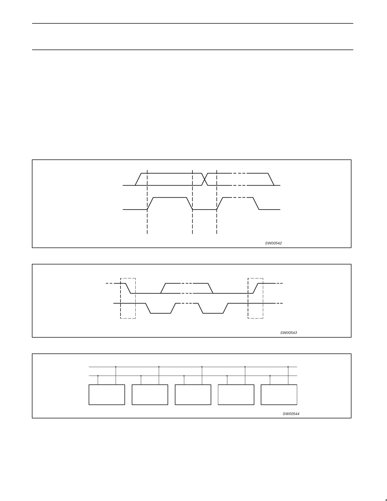
Bit transfer
One data bit is transferred during each clock phase. The data on the
SDA line must remain stable during the HIGH period of the clock
pulse as changes in the data line at this time will be interpreted as
control signals (See Figure 14).
Start and Stop conditions
Both data and clock lines remain HIGH when the bus is not busy. A
HIGH-to-LOW transition of the data line, while the clock is HIGH is
defined as the Start condition (S). A LOW-to-HIGH transition of the
data line while the clock is HIGH is defined as the Stop condition (P)
(see Figure 15).
System configuration
A device generating a message is a “transmitter”, a device receiving
is the “receiver”. The device that controls the message is the
“master” and the devices which are controlled by the master are the
“slaves” (see Figure 16).
SDA
SCL
DATA LINE
STABLE;
DATA VALID
CHANGE
OF DATA
ALLOWED
Figure 14. Bit transfer
SW00542
SDA
SDA
SCL
S
SCL
P
START CONDITION
STOP CONDITION
Figure 15. Definition of start and stop conditions
SW00543
SDA
SCL
MASTER
TRANSMITTER/
RECEIVER
SLAVE
RECEIVER
SLAVE
TRANSMITTER/
RECEIVER
MASTER
TRANSMITTER
Figure 16. System configuration
MASTER
TRANSMITTER/
RECEIVER
SW00544
2004 Sep 30
9
Share Link: 