PCA9536 查看數據表(PDF) - NXP Semiconductors.
零件编号
产品描述 (功能)
生产厂家
PCA9536 Datasheet PDF : 24 Pages
| |||
NXP Semiconductors
PCA9536
4-bit I2C-bus and SMBus I/O port
6. Functional description
Refer to Figure 1 “Block diagram of PCA9536”.
6.1 Registers
6.1.1 Command byte
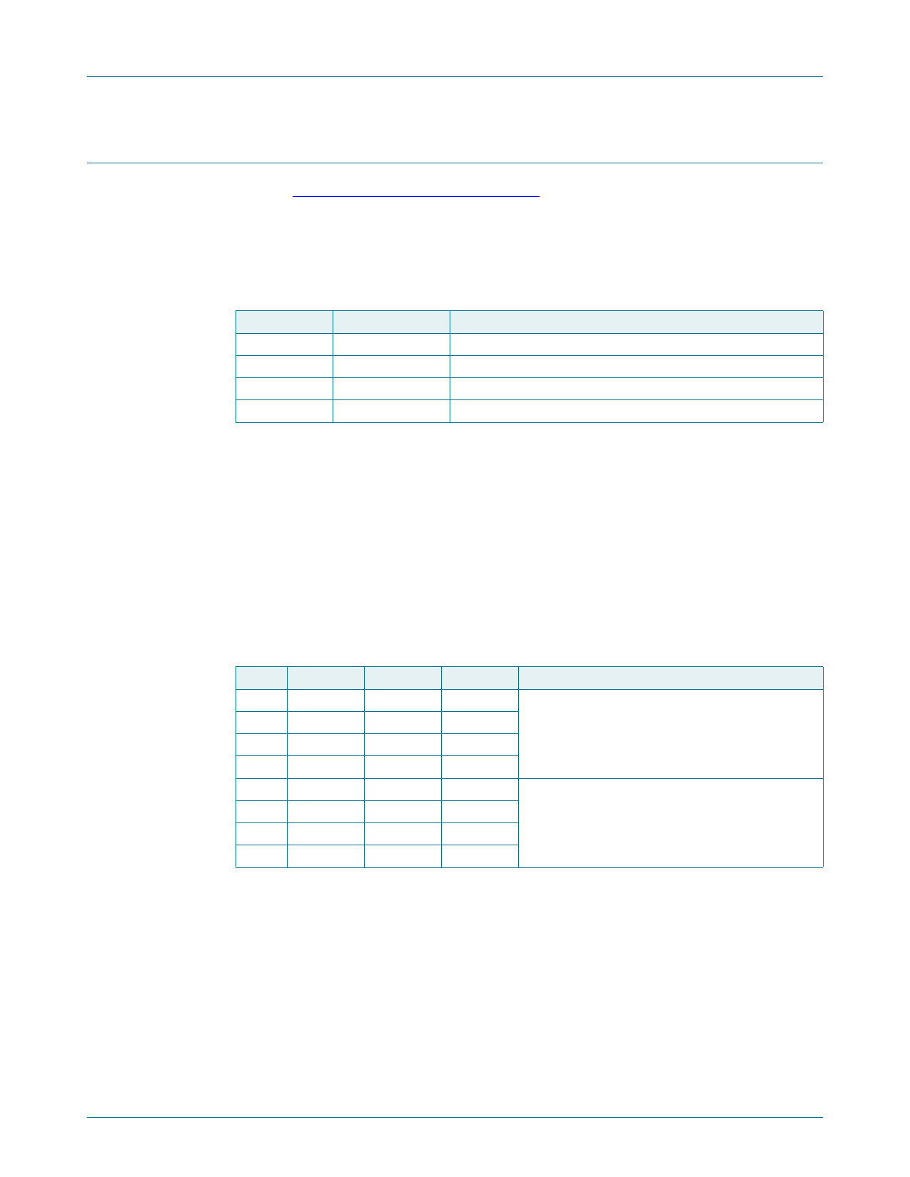
Table 4. Command byte
Command Protocol
0
read byte
1
read/write byte
2
read/write byte
3
read/write byte
Function
Input Port register
Output Port register
Polarity Inversion register
Configuration register
The command byte is the first byte to follow the address byte during a write transmission.
It is used as a pointer to determine which of the following registers will be written or read.
6.1.2 Register 0 - Input Port register
This register is a read-only port. It reflects the incoming logic levels of the pins, regardless
of whether the pin is defined as an input or an output by Register 3. Writes to this register
have no effect.
The default ‘X’ is determined by the externally applied logic level, normally logic 1 when
no external signal externally applied because of the internal pull-up resistors.
Table 5. Register 0 - Input Port register bit description
Legend: * default value
Bit Symbol Access Value
Description
7
I7
read only 1*
not used
6
I6
read only 1*
5
I5
read only 1*
4
I4
read only 1*
3
I3
read only X
determined by externally applied logic level
2
I2
read only X
1
I1
read only X
0
I0
read only X
PCA9536
Product data sheet
All information provided in this document is subject to legal disclaimers.
Rev. 6 — 7 November 2017
© NXP Semiconductors N.V. 2017. All rights reserved.
5 of 24
Share Link: 