PEEL16CV8J-25 查看數據表(PDF) - Anachip Corporation
零件编号
产品描述 (功能)
生产厂家
PEEL16CV8J-25 Datasheet PDF : 11 Pages
| |||
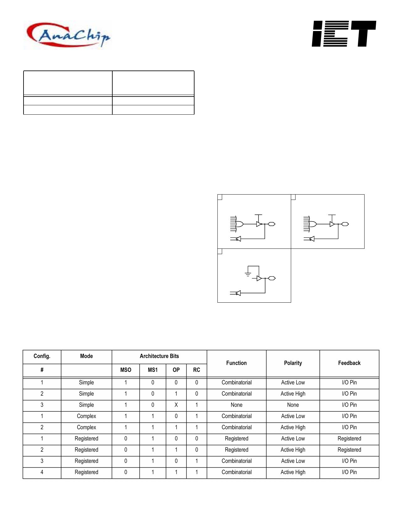
Table 1 : PEEL TM 16CV8 Device Compatibility
PLD Architecture
Compatibility
16RP6
14RP8
PEELTM 16CV8
Device Mode
Registered
Registered
Programmable Macrocell
The macrocell provides complete control over the architecture of each
output. The ability to configure each output independently permits users
to tailor the configuration of the PEELTM 16CV8 to the precise require-
ments of their designs.
Macrocell Architecture
Each macrocell consists of an OR function, a D-type flip-flop, an output
polarity selector, and a programmable feedback path. Four EEPROM
architecture bits MS0, MS1, OP, and RC control the configuration of
each macrocell. Bits MS0 and MS1 are global, and select between Sim-
ple, Complex, and Registered mode for the whole device. Bits OP and
RC are local for each macrocell; bit OP controls the output polarity and bit
RC selects between registered and combinatorial operation and also
specifies the feedback path. Table 2 shows the architecture bit settings
for each possible configuration.
Equivalent circuits for the possible macrocell configurations are illus-
trated in Figures 3, 4, and 5. When creating a PEELTM device design, the
desired macrocell configuration generally is specified explicitly in the
design file. When the design is assembled or compiled, the macrocell
configuration bits are defined in the last lines of the JEDEC program-
ming file.
Simple Mode
In Simple mode, all eight product terms feed the OR array which can
generate a purely combinatorial function for the output pin. The pro-
grammable output polarity selector allows active-high or active-low logic,
eliminating the need for external inverters. For output functions, the
buffer can be permanently enabled. Feedback into the array is available
on all macrocell I/O pins, except for pins 15 and 16. Figure 6 shows the
logic array of the PEELTM 16CV8 configured in Simple mode.
Simple mode also provides the option of configuring an I/O pin as a ded-
icated input. In this case, the output buffer is permanently disabled, and
the I/O pin feedback is used to bring the input signal from the pin into the
logic array. This option is available for all I/O pins except pins 15 and 16.
Figure 3 shows the possible Simple mode macrocell configurations.
1 Simple Mode
Active Low Output
VCC
2 Simple Mode
Active High Output
VCC
3 Simple Mode
I/O Pin Input
Figure 3 - Macrocell Configurations for Simple mode of the PEELTM
16CV8 (see Figure 6 for Logic Array)
Table 2 : PEEL TM 16CV8 Device Mode/Macrocell Configuration Bits
Anachip Corp.
www.anachip.com.tw
Rev. 1.0 Dec 16, 2004
3/11
Share Link: 