LTC1196(Rev_0) 查看數據表(PDF) - Linear Technology
零件编号
产品描述 (功能)
生产厂家
LTC1196 Datasheet PDF : 28 Pages
| |||
LTC1196/LTC1198
UW
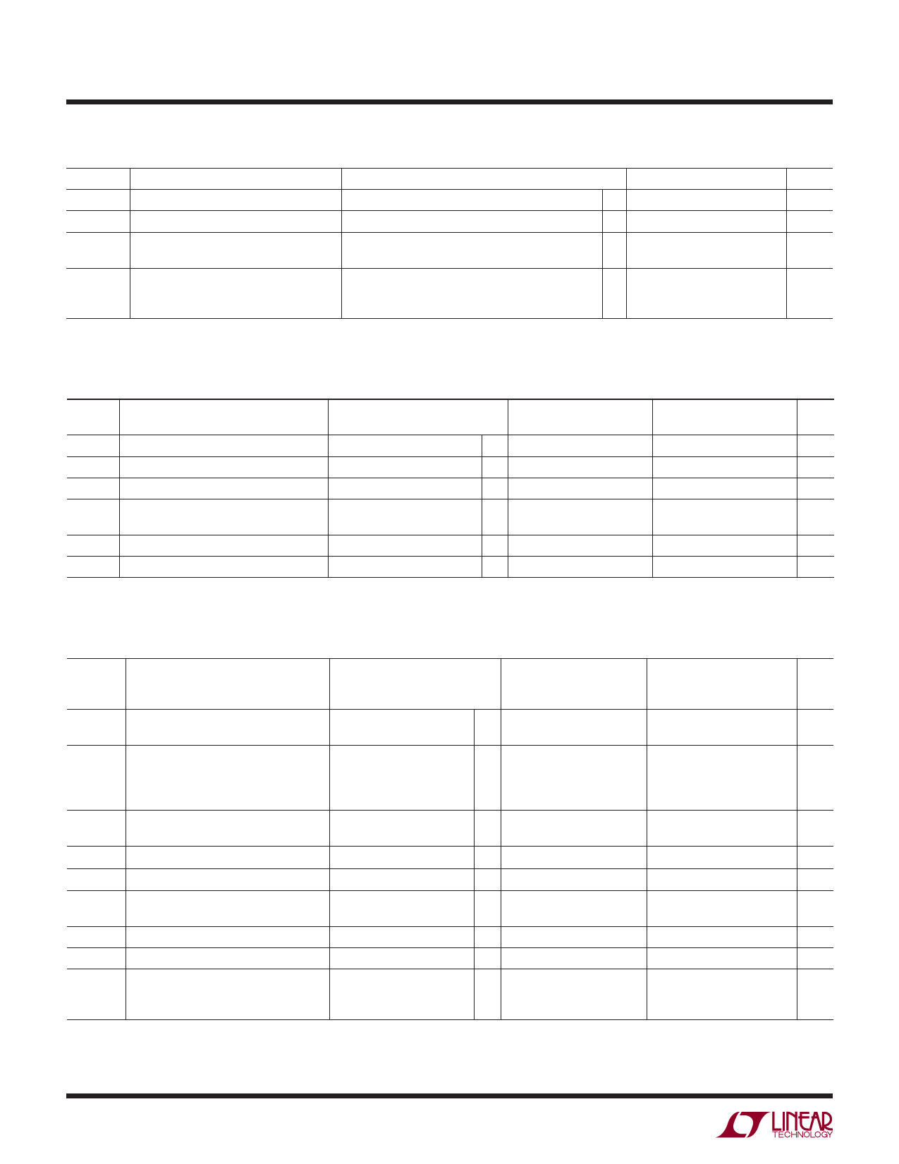
DY A IC ACCURACY
VCC = 2.7V, VREF = 2.5V, fCLK = fCLK(MAX) as defined in Recommended Operating Conditions, unless otherwise noted.
SYMBOL
S/(N + D)
THD
IMD
PARAMETER
Signal-to-Noise Plus Distortion
Total Harmonic Distortion
Peak Harmonic or Spurious Noise
Intermodulation Distortion
Full Power Bandwidth
Full Linear Bandwidth [S/(N + D) > 44dB]
CONDITIONS
190kHz/380kHz Input Signal
190kHz/380kHz Input Signal
190kHz/380kHz Input Signal
fIN1 = 189.37kHz,
fIN2 = 192.446kHz
LTC1196
MIN TYP MAX
47/45
49/47
53/46
51
5
0.5
LTC1198
MIN TYP MAX
47/45
49/47
53/46
51
5
0.5
UNITS
dB
dB
dB
dB
MHz
MHz
AC CHARACTERISTICS
VCC = 2.7V, VREF = 2.5V, fCLK = fCLK(MAX) as defined in Recommended Operating Conditions, unless otherwise noted.
SYMBOL PARAMETER
tCONV
Conversion Time (See Figures 1, 2)
fSMPL(MAX) Maximum Sampling Frequency
tdDO
Delay Time, CLK↑ to DOUT Data Valid
tDIS
Delay Time CS↑ to DOUT Hi-Z
ten
Delay Time, CLK↓ to DOUT Enabled
thDO
Time Output Data Remains Valid
After CLK↑
tr
DOUT Fall Time
tf
DOUT Rise Time
CIN
Input Capacitance
CONDITIONS
LTC1196
LTC1196
LTC1198
LTC1198
CLOAD = 20pF
CLOAD = 20pF
CLOAD = 20pF
CLOAD = 20pF
CLOAD = 20pF
Analog Input On Channel
Analog Input Off Channel
Digital Input
LTC1196-1
LTC1198-1
MIN TYP MAX
1.58
q
1.85
450
q 383
337
q 287
100 150
q
180
q
110 220
q
80 130
q 45 90
q
10 30
q
10 30
30
5
5
LTC1196-2
LTC1198-2
MIN TYP MAX
2.13
2.84
333
250
250
187
130 200
250
120 250
100 200
45 120
15 40
15 40
30
5
5
UNITS
µs
µs
kHz
kHz
kHz
kHz
ns
ns
ns
ns
ns
ns
ns
pF
pF
pF
The q denotes specifications which apply over the full operating
temperature range.
Note 1: Absolute maximum ratings are those values beyond which the life
of a device may be impaired.
Note 2: All voltage values are with respect to GND.
Note 3: Integral nonlinearity is defined as deviation of a code from a
straight line passing through the actual endpoints of the transfer curve.
The deviation is measured from the center of the quantization band.
Note 4: Total unadjusted error includes offset, full scale, linearity,
multiplexer and hold step errors.
Note 5: Channel leakage current is measured after the channel selection.
6
Share Link: 