LTC1196 查看數據表(PDF) - Linear Technology
零件编号
产品描述 (功能)
生产厂家
LTC1196 Datasheet PDF : 28 Pages
| |||
LTC1196/LTC1198
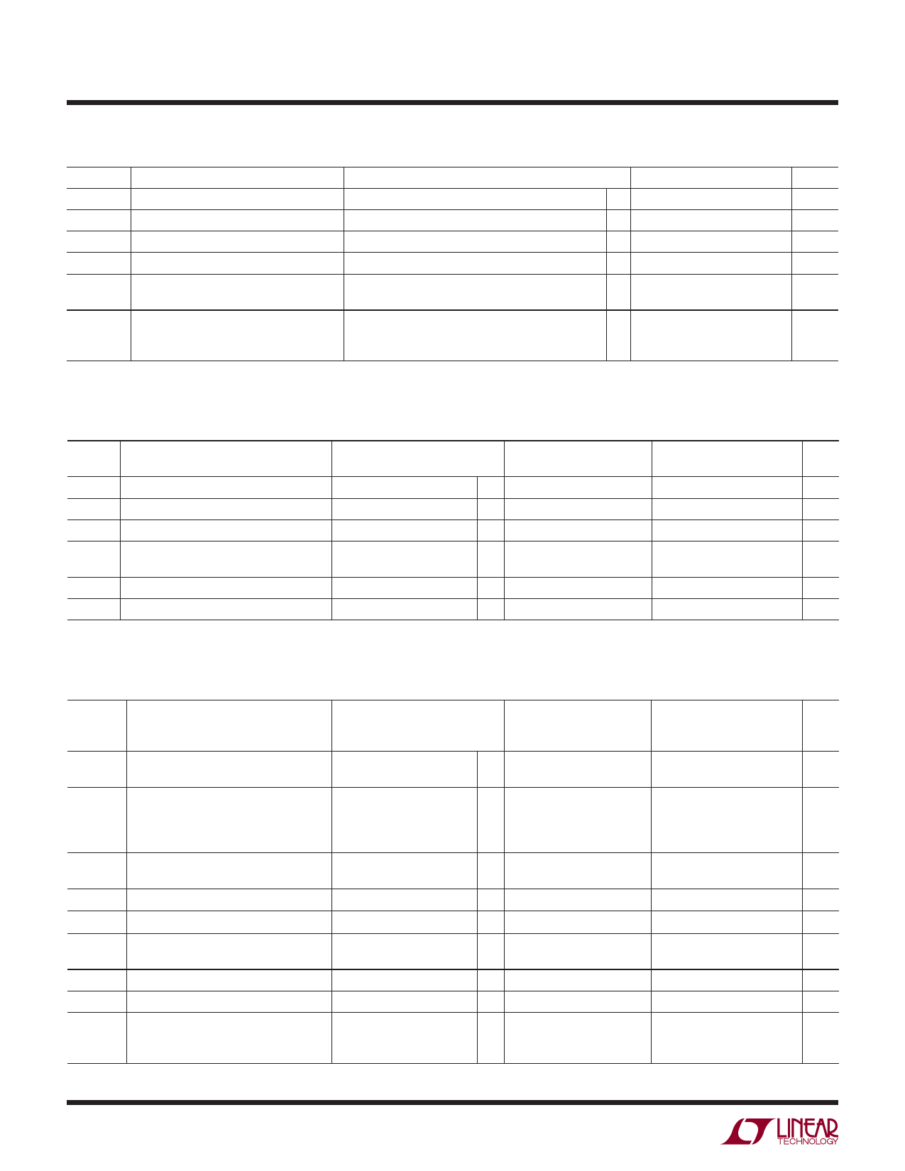
DIGITAL AND DC ELECTRICAL CHARACTERISTICS The l denotes the specifications which
apply over the full operating temperature range, otherwise specifications are at TA = 25°C. VCC = 5V, VREF = 5V, unless otherwise noted.
SYMBOL PARAMETER
CONDITIONS
MIN TYP MAX UNITS
VOL
Low Level Output Voltage
IOZ
Hi-Z Output Leakage
VCC = 4.75V, IO = 1.6mA
CS = High
l
0.4
V
l
±3
μA
ISOURCE Output Source Current
VOUT = 0V
–25
mA
ISINK
Output Sink Current
VOUT = VCC
45
mA
IREF
Reference Current, LTC1196
CS = VCC
fSMPL = fSMPL(MAX)
l
0.001
3
μA
l
0.5
1
mA
ICC
Supply Current
CS
CS
=
=
VCC,
VCC,
LTC1198
LTC1196
(Shutdown)
l
0.001
3
μA
l
7
15
mA
fSMPL = fSMPL(MAX), LTC1196/LTC1198
l
11
20
mA
DYNAMIC ACCURACY The l denotes the specifications which apply over the full operating temperature range,
otherwise specifications are at TA = 25°C. VCC = 5V, VREF = 5V, fCLK = fCLK(MAX) as defined in Recommended Operating Conditions,
unless otherwise noted.
SYMBOL PARAMETER
CONDITIONS
S/(N + D) Signal-to-Noise Plus Distortion
500kHz/1MHz Input Signal
THD
Total Harmonic Distortion
500kHz/1MHz Input Signal
Peak Harmonic or Spurious Noise
500kHz/1MHz Input Signal
IMD
Intermodulation Distortion
Full-Power Bandwidth
fIN1 = 499.37kHz
fIN2 = 502.446kHz
Full Linear Bandwidth [S/(N + D) > 44dB
LTC1196
LTC1198
MIN TYP MAX MIN TYP MAX UNITS
47/45
47/45
dB
49/47
49/47
dB
55/48
55/48
dB
51
51
dB
8
8
MHz
1
1
MHz
AC CHARACTERISTICS The l denotes the specifications which apply over the full operating temperature range,
otherwise specifications are at TA = 25°C. VCC = 5V, VREF = 5V, fCLK = fCLK(MAX) as defined in Recommended Operating Conditions,
unless otherwise noted.
SYMBOL PARAMETER
tCONV
Conversion Time (See Figures 1, 2)
CONDITIONS
fSMPL(MAX) Maximum Samping Frequency
tdDO
Delay Time, CLK↑ to DOUT Data Valid
LTC1196
LTC1196
LTC1198
LTC1198
CLOAD = 20pF
tDIS
Delay Time CS↑ to DOUT Hi-Z
ten
Delay Time, CLK↓ to DOUT Enabled
CLOAD = 20pF
thDO
Time Output Data Remains Valid After CLOAD = 20pF
CLK↑
tf
DOUT Fall Time
tr
DOUT Rise
CIN
Input Capacitance
CLOAD = 20pF
CLOAD = 20pF
Analog Input On Channel
Analog Input Off Channel
Digital Input
LTC1196-1
LTC1198-1
MIN TYP MAX
LTC1196-2
LTC1198-2
MIN TYP MAX UNITS
600
l
710
710
ns
900
ns
1.20
1.00
MHz
l 1.00
0.80
MHz
0.90
0.75
MHz
l 0.75
0.60
MHz
55
64
l
73
68
78
ns
94
ns
l
70
120
88
150
ns
l
30
50
43
63
ns
l 30
45
30
55
ns
l
5
15
l
5
15
30
5
5
10
20
ns
10
20
ns
30
pF
5
pF
5
pF
119698fa
4
Share Link: 