PT6524LQ 查看數據表(PDF) - Princeton Technology
零件编号
产品描述 (功能)
生产厂家
PT6524LQ Datasheet PDF : 24 Pages
| |||
PT6524
DR: BIAS DRIVE TECHNIQUR CONTROL DATA BIT
This control bit is used to select either 1/2 Bias drive or 1/3 Bias Drive Technique. Please refer to the table below.
DR
Bias Drive Technique
0
1/3
1
1/2
SC: SEGMENT ON / OFF CONTROL DATA BIT
This control bit is used to select the state of the segment driver output pins. Please refer to the table below.
SC
Display State
0
ON
1
OFF
BU: NORMAL / POWER SAVING MODE SELECT BIT
This control bit is used to select either the Normal Mode or the Power Saving Mode. Please refer to the table below.
BU
Mode
Remarks
0
Normal Mode
-
The oscillation circuit stops, the common and segment output pins are set to
1
Power Saving Mode
“LOW” level. It must be noted that the output pins - SG1/P1 to SG12/P12
may be used as General Purpose Output Ports by setting the control bits –
P0 to P3.
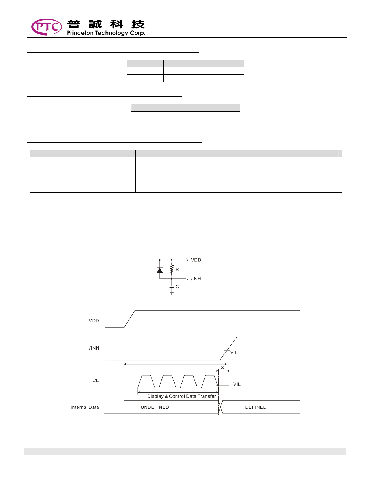
DISPLAY CONTROL AND THE /INH PIN
When power is initialized, the internal data of PT6524 (that is, display data – D1 to D204 and the control data) are not
defined. Irrelevant displays caused by the undefined internal data can be prevented by using the following procedures.
The /INH pin must be set to “LOW” at the same the as the power is applied to turn OFF the display. Doing this will set the
output pins – SG1/P1 to SG12/P12, SG13 to SG51 and COM1 to COM4 to “LOW” level. While the /INH pin is held at
“LOW” level, the microcontroller must send the serial data. Then the application can set the /INH pin to “HIGH”. Please
refer to the figure below.
Notes:
1. t1 = determined by the value of C and R.
2. tc = 10us (minimum)
V1.3
10
Share Link: 