MDD142 查看數據表(PDF) - IXYS CORPORATION
零件编号
产品描述 (功能)
生产厂家
MDD142 Datasheet PDF : 3 Pages
| |||
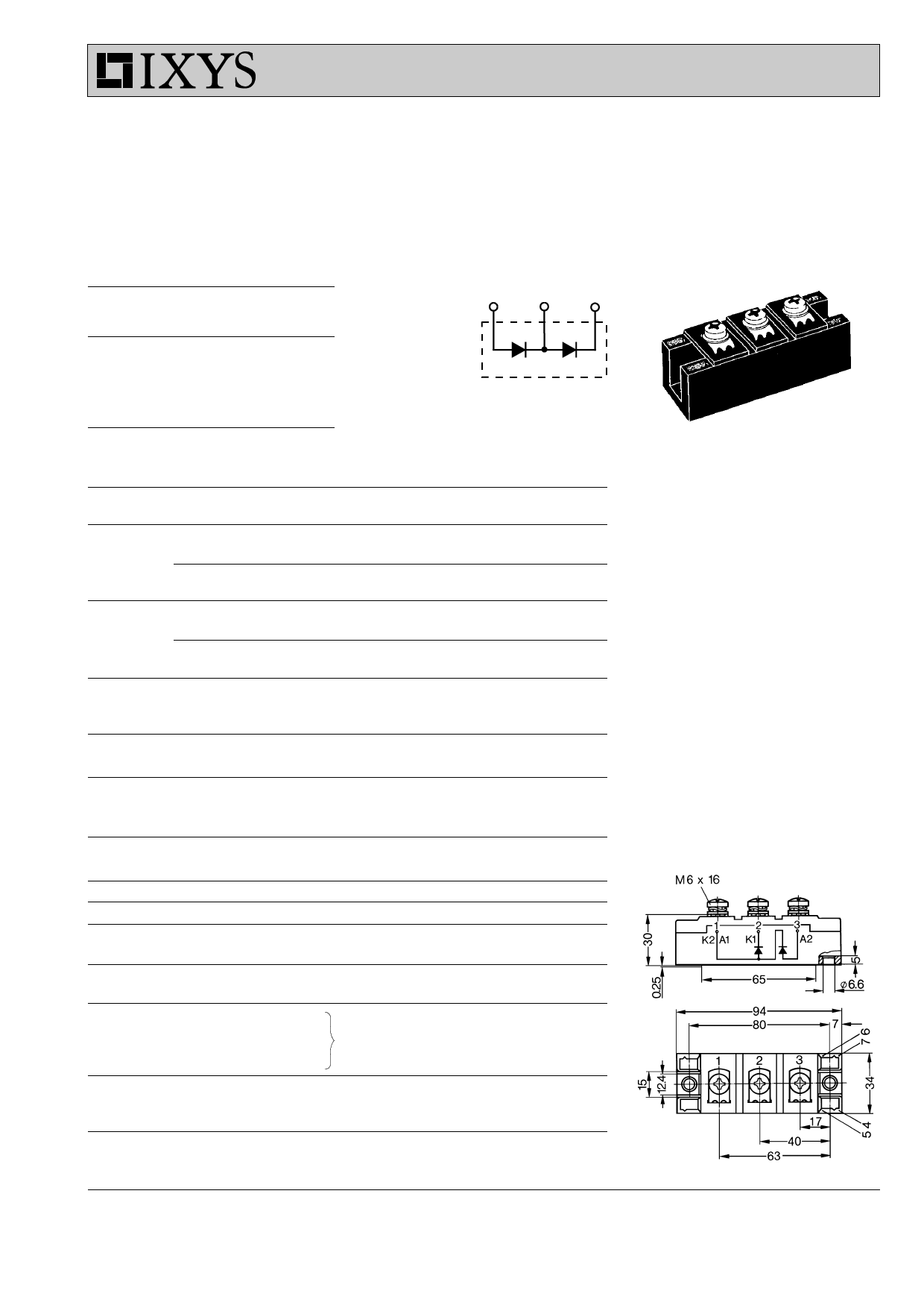
MDD 142
High Power
Diode Modules
IFRMS = 2x 300 A
IFAVM = 2x 165 A
VRRM = 800-1800 V
VRSM
V
900
1300
1500
1700
1900
VRRM
V
800
1200
1400
1600
1800
Type
MDD 142-08N1
MDD 142-12N1
MDD 142-14N1
MDD 142-16N1
MDD 142-18N1
3
1
2
3
2
1
Symbol
IFRMS
I
FAVM
IFSM
òi2dt
TVJ
TVJM
Tstg
V
ISOL
Md
Weight
Symbol
IR
VF
VT0
r
T
QS
IRM
RthJC
RthJK
dS
dA
a
Test Conditions
TVJ = TVJM
T
C
=
100°C;
180°
sine
TVJ = 45°C;
VR = 0
t = 10 ms (50 Hz), sine
t = 8.3 ms (60 Hz), sine
TVJ = TVJM
VR = 0
t = 10 ms (50 Hz), sine
t = 8.3 ms (60 Hz), sine
T
VJ
=
45°C
VR = 0
t = 10 ms (50 Hz), sine
t = 8.3 ms (60 Hz), sine
TVJ = TVJM
V =0
R
t = 10 ms (50 Hz), sine
t = 8.3 ms (60 Hz), sine
Maximum Ratings
300
A
165
A
4700
A
5000
A
4100
A
4300
A
110 000
A2s
104 000
A2s
84 000
A2s
77 000
A2s
-40...+150
°C
150
°C
-40...+125
°C
50/60 Hz, RMS
t = 1 min
IISOL £ 1 mA
t=1s
Mounting torque (M6)
Terminal connection torque (M6)
Typical including screws
3000
V~
3600
V~
2.25-2.75/20-25 Nm/lb.in.
4.5-5.5/40-48 Nm/lb.in.
120
g
Test Conditions
TVJ = TVJM; VR = VRRM
IF = 300 A; TVJ = 25°C
For power-loss calculations only
T =T
VJ
VJM
TVJ = 125°C; IF = 300 A, -di/dt = 50 A/ms
per diode; DC current
per module
per diode; DC current
per module
other values
see Fig. 6/7
Creepage distance on surface
Strike distance through air
Maximum allowable acceleration
Characteristic Values
20 mA
1.3 V
0.8 V
1.3 mW
550 mC
235 A
0.21 K/W
0.105 K/W
0.31 K/W
0.155 K/W
12.7 mm
9.6 mm
50 m/s2
Features
q International standard package
q Direct copper bonded Al2O3 -ceramic
base plate
q Planar passivated chips
q Isolation voltage 3600 V~
q UL registered, E 72873
Applications
q Supplies for DC power equipment
q DC supply for PWM inverter
q Field supply for DC motors
q Battery DC power supplies
Advantages
q Space and weight savings
q Simple mounting
q Improved temperature and power
cycling
q Reduced protection circuits
Dimensions in mm (1 mm = 0.0394")
Data according to IEC 60747 and refer to a single diode unless otherwise stated.
IXYS reserves the right to change limits, test conditions and dimensions
© 2000 IXYS All rights reserved
1-3
Share Link: 