RE46C144 查看數據表(PDF) - Microchip Technology
零件编号
产品描述 (功能)
生产厂家
RE46C144 Datasheet PDF : 26 Pages
| |||
RE46C144
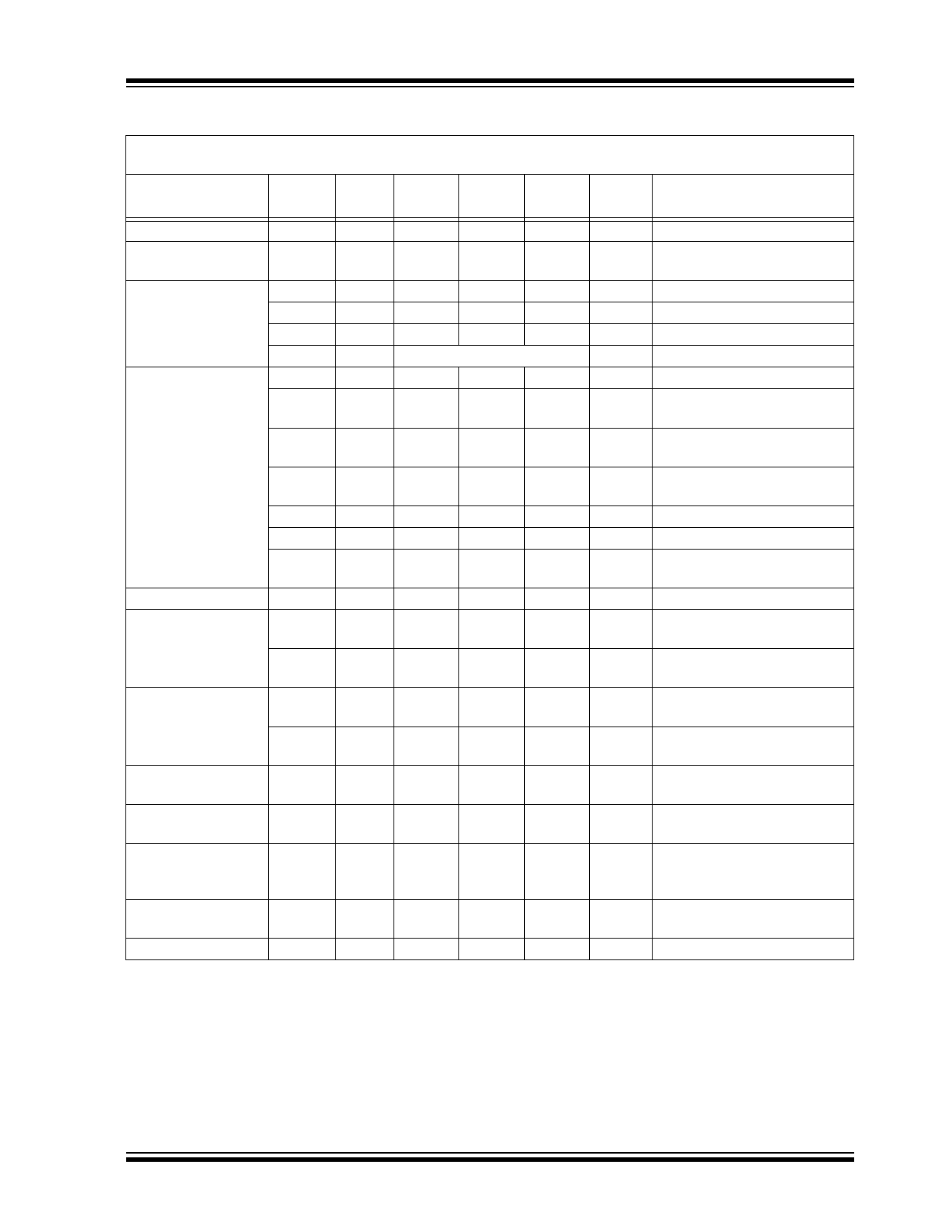
TABLE 1-1: AC ELECTRICAL CHARACTERISTICS
AC Electrical Characteristics: Unless otherwise indicated, all parameters apply at TA = -25°C to +75°C, VDD = 9V,
VSS = 0V, Component Values from Typical Application; R9 = 100 K, R12 = 10 M, C5 = 1.5 nF.
Parameter
Symbol
Test
Pin
Min
Typ
Max Units
Conditions
Oscillator Period
TPOSC
12
9.4
LED and
STROBE On Time
TON1
11, 4
9.4
10.5
11.5
10.5
11.5
ms No alarm condition
ms Operating
LED Period
TPLED1
11
TPLED2
11
TPLED3
11
TPLED4
11
STROBE and IRED
TPER1
4, 6
Pulse Period
TPER1A 4, 6
39
43
47
.6
.67
.74
9.6
10.75
11.8
LED IS NOT ON
9.6
10.75
11.8
2.42
2.7
2.96
s Standby, no alarm
s Local alarm condition
s Timer mode, no local alarm
s Remote alarm only
s Standby, no alarm
s Standby, after one valid smoke
sample
TPER1B 4, 6
1.21
1.33
1.47
s Standby, after two consecutive
valid smoke samples
TPER2
4, 6
1.21
1.33
1.47
s In Local Alarm (three consecu-
tive valid smoke samples)
IRED On Time
TPER3
4, 6
9.7
TPER4
4, 6
300
TPER5
4, 6
39
TON2
6
94
10.5
11.8
336
370
47
104
115
s In Remote Alarm
ms Push-button Test
s Chamber Test or Low-battery
Test, no alarms
µs Operating
Horn On Time
THON1
8, 9
227
THON2
8, 9
9.5
252
277
10.5
11.5
ms Operating, alarm condition,
Note 1
ms Low Battery or Failed Chamber
Test, no alarm
Horn Off Time
THOF1
8, 9
76
84
92
ms Operating, Alarm Condition,
Note 1
THOF3
8, 9
39
43
47
s Low Battery or Failed Chamber
Test, no alarm
IO Charge Dump
TIODMP
7
.91
Duration
1.46
s At conclusion of local alarm or
test
IO Delay
TIODLY1
7
0
s From start of local alarm to IO
Active
IO Filter
TIOFILT
7
600
ms IO pulse-width ensured to be
filtered. IO as input, no local
alarm
Remote Alarm Delay TIODLY2
7
.75
1.65
s No local alarm, from IO Active
to Horn Active
Timer Period
TTPER
7
8.5
10
Min No alarm condition, Note 2
Note 1: See timing diagram for Horn Temporal Pattern
2: During the Timer mode, the LED period is 10.5 seconds. The LED period will return to 43 seconds at the
conclusion of the Timer mode.
3: TPOSC and TON2 are 100% production tested. All other timing is guaranteed by functional testing.
4: Typical values are for design information and are not ensured.
5: Limits over the specified temperature range are not production tested and are based on characterization
data.
2009-2012 Microchip Technology Inc.
DS22180C-page 5
Share Link: 