RS5RM1817A-T2 查看數據表(PDF) - RICOH Co.,Ltd.
零件编号
产品描述 (功能)
生产厂家
RS5RM1817A-T2 Datasheet PDF : 30 Pages
| |||
RS5RM
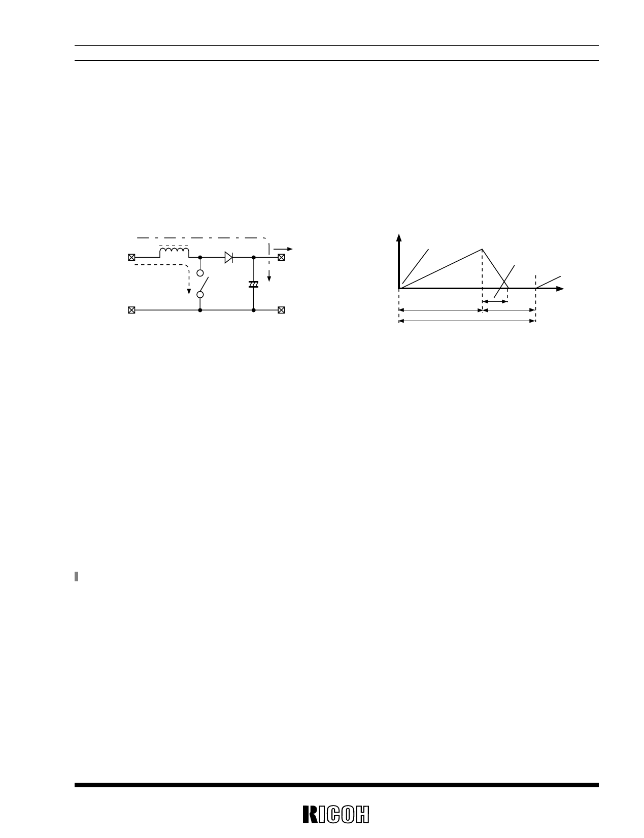
OPERATION OF STEP-UP DC/DC CONVERTER
Step-up DC/DC Converter charges energy in the inductor when Lx Transistor (LxTr) is ON, and discharges the
energy with the addition of the energy from Input Power Source thereto when LxTr is OFF, so that a higher out-
put voltage than the input voltage is obtained.
The operation will be explained with reference to the following diagrams :
< Basic Circuits >
< Current through L >
i2
L
SD
IOUT
VIN
i1
VOUT
LX Tr
CL
IL
IL min
ton
IL max
topen
t
toff
T=1/ fosc
Step.1: LxTr is turned ON and current IL (=i1 ) flows, so that energy is charged in L. At this moment, IL(=i1 ) is
increased from ILmin (=0) to reach ILmax in proportion to the on-time period (ton) of LxTr.
Step.2: When LxTr is turned OFF, Schottky diode (SD) is turned ON in order that L maintains IL at ILmax, so that
current IL (=i2) is released.
Step.3: IL (=i2) is gradually decreased, and in the case of discontinuous mode, IL reaches ILmin (=0) after a time
period of topen, so that SD is turned OFF. In the case of a continuous mode,the time period (toff) runs out
before IL reaches ILmin (=0), so that LxTr is turned ON in the next cycle, and SD is turned OFF. In this
case, ILmin does not reach zero, and IL (=i1) increases from ILmin (>0).
In the case of PWM control system, with the oscillator frequency (fosc) maintained constant, the output volt-
age is maintained constant by controlling the on-time period (ton).
(Note) Please refer to the Application Manual for “RH5RH SERIES” for details.
7
Share Link: 