SFH4555_ 查看數據表(PDF) - OSRAM GmbH
零件编号
产品描述 (功能)
生产厂家
SFH4555_ Datasheet PDF : 14 Pages
| |||
devices, whereas the latter uses narrow-
angle IREDs, necessary to achieve total
internal reflection. It is worth to mention that
the emitting light guides radiation
characteristics depend on the design of the
outcoupling structures and the emitter’s
radiation characteristics in combination with
the coupling arrangement. To support
design activities OSRAM provides raytrace
models, available at the OSRAM website.
For narrow-angle applications, the e.g.
MIDLED® SFH46XX series provides a viable
solution, whereas the TOPLED® SFH42XX
without lens family is an excellent choice for
standard wide-angle requirements. Both
feature slim packages and a flat-top to
minimize the air-gap between the fiber and
the IRED.
3.4 Projector-based with Diffuse
Illumination
In projector-based touchscreens with IR
illumination from the backside it is desirable
to achieve a diffuse and homogenous
illumination. Suitable high power products
are the DRAGON IRED series (SFH423X).
In large projector applications it is
recommended to split the screen into
subscreens and use several IRED-arrays for
illumination purpose. Alternatively high
power IRED-based modules with
homogenous and diffuse fields are
recommended, like the OSRAM OSTAR®
Observation product family (SFH47XX).
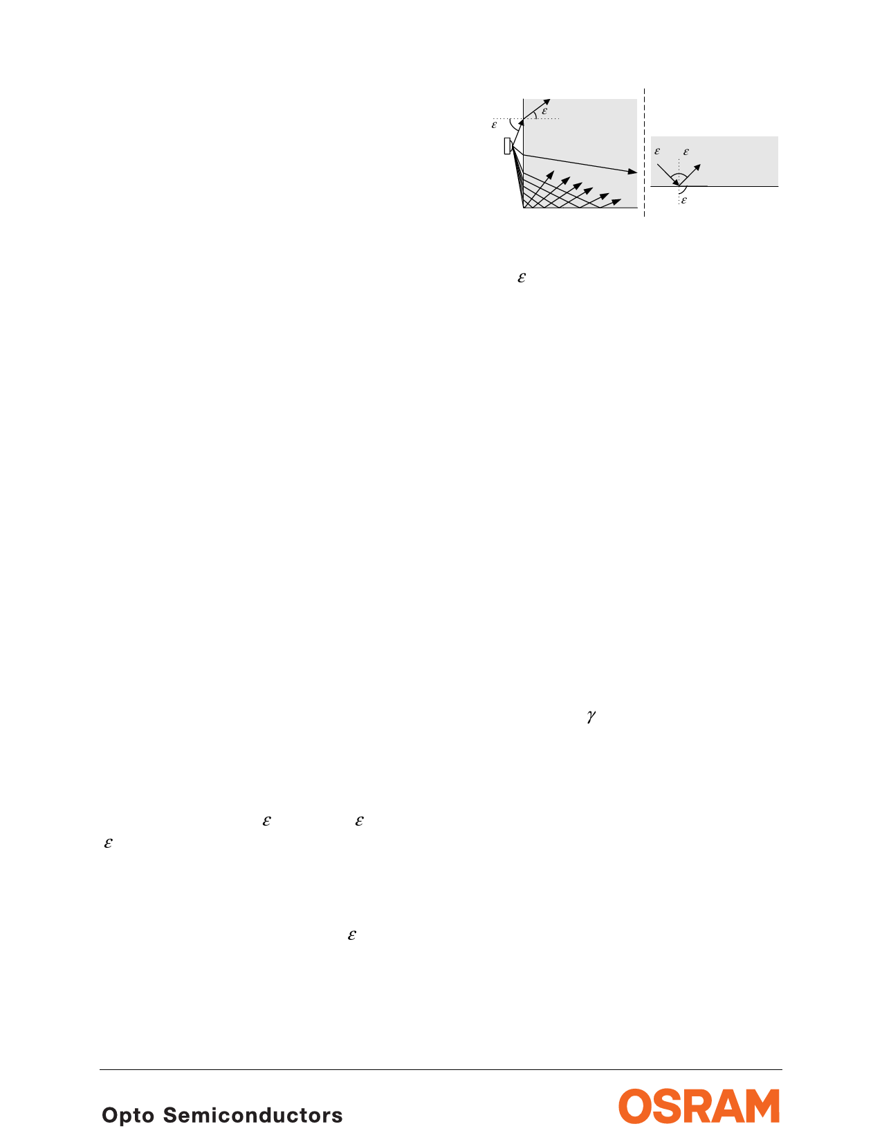
3.5 Projector-based with FTIR
The FTIR principle features different
aspects. The mathematics behind is based
on Snell’s law: n1·sin(ε 1) = n2·sin(ε 2), with
ε as the angle between the surface normal
and the light path and n as the refractive
index of the material (see Fig. 6 for an
illustration). Using Snell’s law, the boundary
condition for total internal reflection at the
glass – air interface is around ε c = 42°
(assuming a refractive index of around n2 =
1.49 for acrylic glass).
refraction
n1=1.0 ε 2
ε1
IRED
n2=1.5
total
internal reflection
ε1= εc
total internal reflection
n2=1.5
ε 2 = 90° n1=1.0
Fig. 6: Definition of Snell’s law and critical
angle ε c for total internal reflection. The left
schematic also illustrates that under certain
conditions all light coupled into the light
guide is subject to total internal reflection.
To achieve efficient FTIR a high number of
total internal reflections per unit length inside
the acrylic glass are desirable.
Direct coupling (also called butt coupling,
like depicted on the left side in Fig. 5),
employs IREDs with a wide half-angle to
achieve this target.
However, to increase the level of internal
reflections (increasing the light density to
achieve a more efficient FTIR) it might be
preferable to couple light into the acrylic
glass under angled conditions. This can be
achieved efficiently by either tilting the
standard wide-angle emitter by e.g. 45° or
by an inclined glass edge (see also Fig. 5,
coupling from the right side). A suitable
arrangement is e.g. cutting the glass edge
up to around γ g ≈ 35°. To ensure a
maximum of total internal reflections
simultaneously with a high power density,
components with a high radiant intensity and
narrow half-angle are recommended. Under
above conditions, emitters with a half-angle
of up to around 15° are preferable.
Compared to wide-angle emitters, narrow-
angle IREDs might require a tighter
component spacing to avoid ‘dark’ spots
close to the coupling location.
To ensure a high coupling efficiency and
minimal Fresnel-losses (which typ. add up to
at least 2 x 4 % at the emitter – air-gap –
glass interfaces) a plain cut glass surface is
August 13, 2010
page 6 of 14
Share Link: 