JAN137K 查看數據表(PDF) - Microsemi Corporation
零件编号
产品描述 (功能)
生产厂家
JAN137K Datasheet PDF : 6 Pages
| |||
SG137A/SG137 SERIES
APPLICATION INFORMATION (continued)
the SG137A flows from input to output. If this current is not
absorbed by the load, the output of the regulator will rise above
the regulated value. The current drawn by R and R is normally
1
2
high enough to absorb the current, but care must be taken in no–
load situations where R1 and R2 have high values. The maximum
value for the operating current, which must be absorbed, is 5mA
for the SG137A, If input-output voltage differential is less than
10V, the operating current that must be absorbed drops to 3mA.
The output stability, load regulation, line regulation, thermal
EXAMPLES:
1. A precision 10V regulator to supply up to 1Amp load current.
a. Select R1 = 100Ω to minimize effect of IADJ
b.
Calculate
R
2
=
VOUT - VREF
(VREF/R1) + IADJ
=
10V - 1.25V =
(1.25V/100W) + 65mA
704W
2. A 15V regulator to run off batteries and supply 50mA.
VIN MAX = 25V
a. To minimize battery drain, select R as high as possible
1
1.25V
R1 = 3mA = 417Ω, use 404Ω, 1%
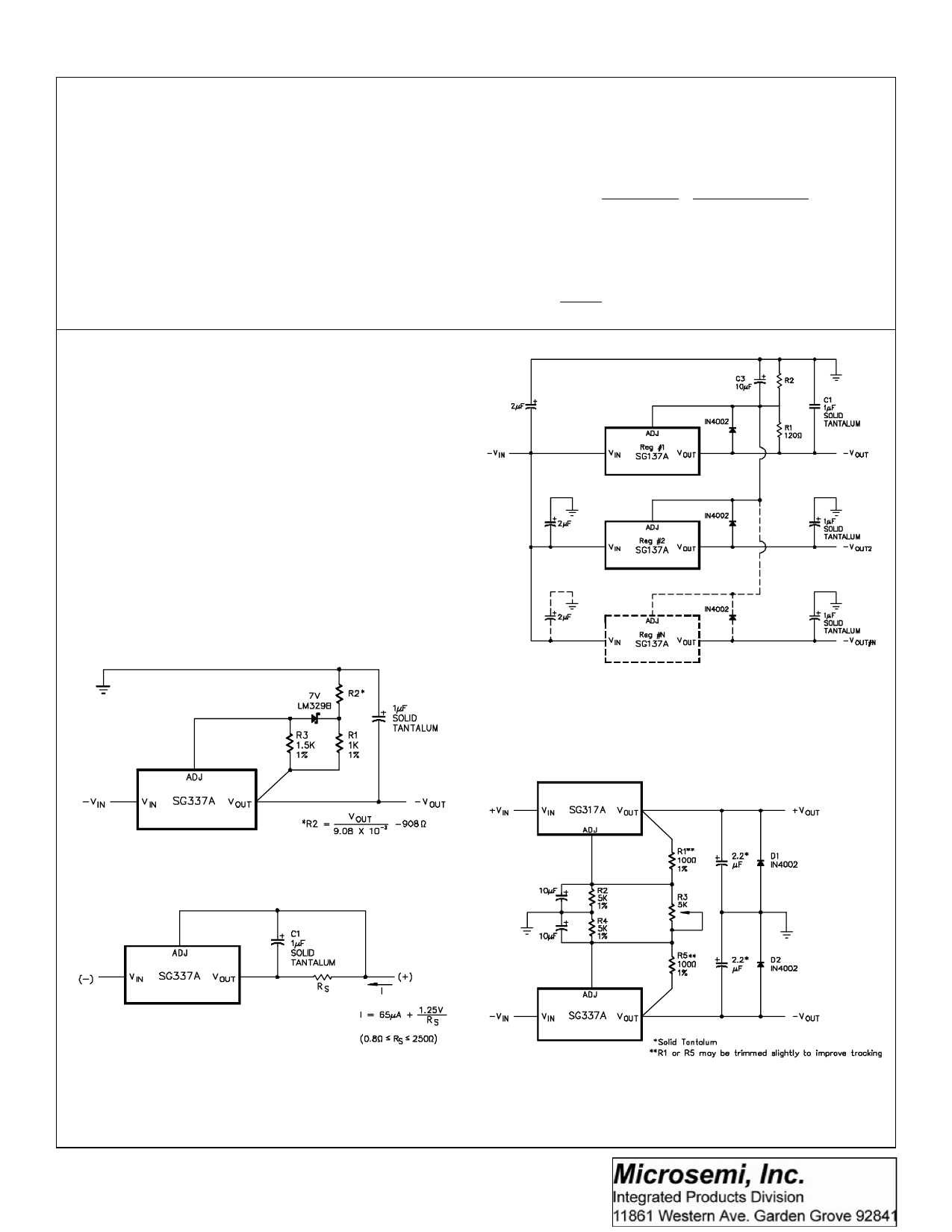
TYPICAL APPLICATIONS
regulation, temperature drift, long term drift, and noise, can be
improved by a factor of 6.6 over the standard regulator configu-
ration. This assumes a zener whose drift and noise is considera-
bly better than the regulator itself. The LM329B has 20PPM/°C
maximum drift and about 10 times lower noise than the regulator.
In the application shown Figure 8, regulators #2 to #N will track
regulator #1 to within ±24mV initially, and to ±60mV over all load,
line, and temperature conditions. If any regulator output is
shorted to ground, all other outputs will drop to -2V. Load
regulation of regulators #2 to #N will be improved by VOUT/1.25V
compared to a standard regulator, so regulator #1 should be the
one which has the lowest load current.
FIGURE 8 - MULTIPLE TRACKING REGULATORS
FIGURE 9 - HIGH STABILITY REGULATOR
FIGURE 10 - CURRENT REGULATOR
2/92 Rev 1.1 2/94
Copyright © 1994
FIGURE 11 - DUAL TRACKING SUPPLY ±1.25V to ±20V
LINFINITY Microelectronics Inc.
5
11861 Western Avenue ∞ Garden Grove, CA 92841
(714) 898-8121 ∞ FAX: (714) 893-2570
Share Link: 