SMA7036M 查看數據表(PDF) - Sanken Electric co.,ltd.
零件编号
产品描述 (功能)
生产厂家
SMA7036M Datasheet PDF : 7 Pages
| |||
2-Phase Stepper Motor Unipolar Driver IC (2-Phase Excitation)
Application Notes
SMA7036M
sOutline
SMA7036M is a stepper motor driver IC developed to reduce
the number of external parts required by the conventional
SMA7029M. This IC successfully eliminates the need for some
external parts without sacrificing the features of SMA7029M.
The basic function pins are compatible with those of SMA7029M.
sNotes on Replacing SMA7029M
SMA7036M is pin-compatible with SMA7029M. When using
the IC on an existing board, the following preparations are nec-
essary:
(1) Remove the resistors and capacitors attached for setting
the chopping OFF time. (r3, r4, C1, and C2 in the catalog)
(2) Remove the resistors and capacitors attached for preventing
noise in the detection voltage VRS from causing malfunction-
ing and short the sections from which the resistors were re-
moved using jumper wires. (r5, r6, C3, and C4 in the catalog)
(3) Normally, keep pins 2 and 11 grounded because their func-
tions have changed to synchronous and asynchronous
switching (SYNC terminals). For details, see "Circuit for Pre-
venting Abnormal Noise When the Motor Is Not Running (Syn-
chronous circuit)." (Low: asynchronous, High: synchronous)
sCircuit for Preventing Abnormal Noise When the
Motor Is Not Running (Synchronous Circuit)
A motor may generate abnormal noise when it is not running.
This phenomenon is attributable to asynchronous chopping be-
tween phases A and B. To prevent the phenomenon, SMA7036M
contains a synchronous chopping circuit. Do not leave the SYNC
terminals open because they are for CMOS input.
5V
R1
VREF
R2
3 REF_A
14 REF_B
VREF waveform
40 Ω
(typ.)
40 Ω
(typ.)
VREF
0
sSynchronous circuit operating waveform
VREF
Phase A 0
VRS
VREF
Phase B 0
VRS
Synchronous circuit OFF
Synchronous circuit ON
Connect TTL or similar to the SYNC terminals and switch the
SYNC terminal level high or low.
When the motor is not running, set the TTL signal high (SYNC
terminal voltage: 4 V or more) to make chopping synchronous.
When the motor is running, set the TTL signal low (SYNC terminal
voltage: 0.8 V or less) to make chopping asynchronous. If chop-
ping is set to synchronous when the motor is running, the motor
torque deteriorates before the coil current reaches the set value.
If no abnormal noise occurs when the motor is not running,
ground the SYNC terminals (TTL not necessary).
TTL, etc.
SYNC_A
SYNC_B
SMA7036M
SYNC voltage : Low → Chopping asynchronous
SYNC voltage : High → Chopping synchronous
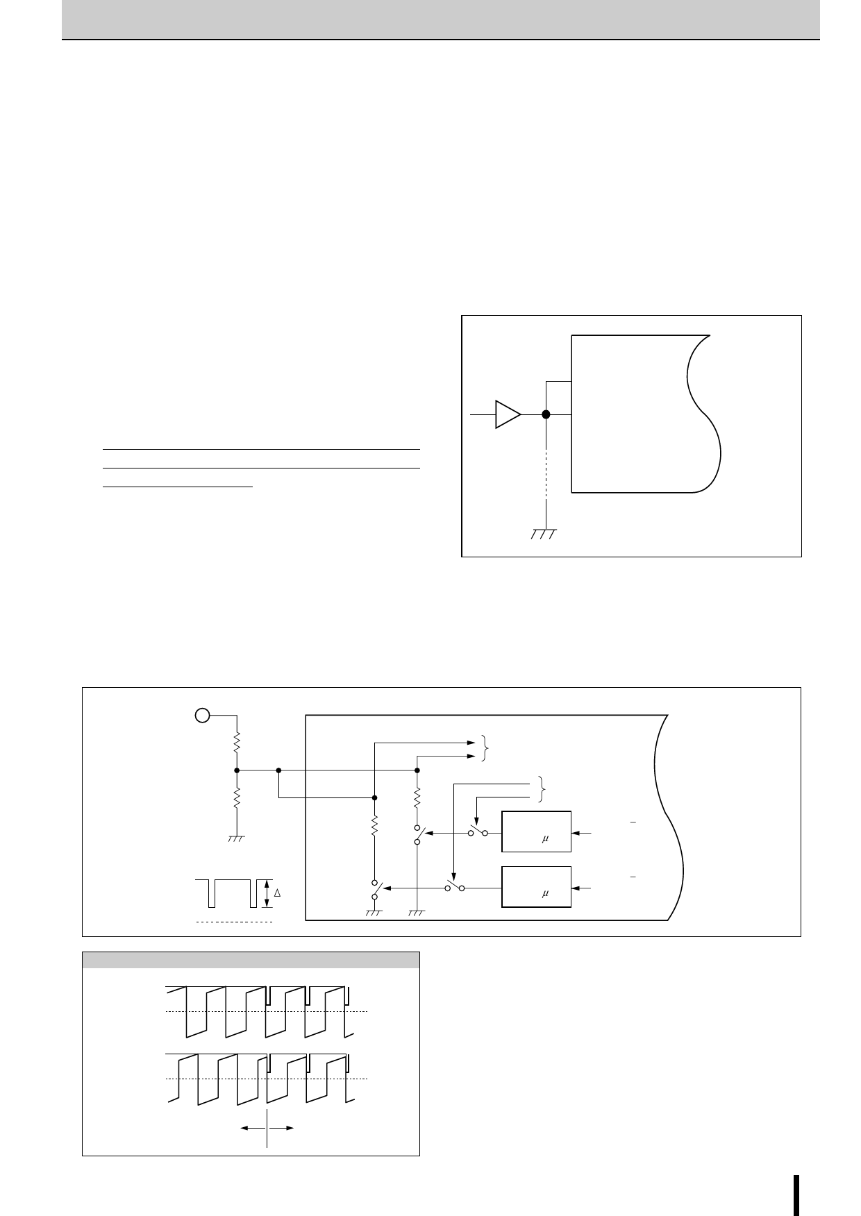
The built-in synchronous chopping circuit superimposes a trigger
signal on the REF terminal for synchronization between the two
phases. The figure below shows the internal circuit of the REF
terminal. Since the ∆ VREF varies depending on the values of R1
and R2, determine these values for when the motor is not run-
ning within the range where the two phases are synchronized.
To comparator
(high impedance)
SMA7036M
Sync/async
switching signal
ONE SHOT
(tw=2 µ S)
FET A/A
gate drive signal
ONE SHOT
(tw=2 µ S)
FET B/B
gate drive signal
SMA7036M 15
Share Link: 