SN74LS353D 查看數據表(PDF) - Motorola => Freescale
零件编号
产品描述 (功能)
生产厂家
SN74LS353D Datasheet PDF : 6 Pages
| |||
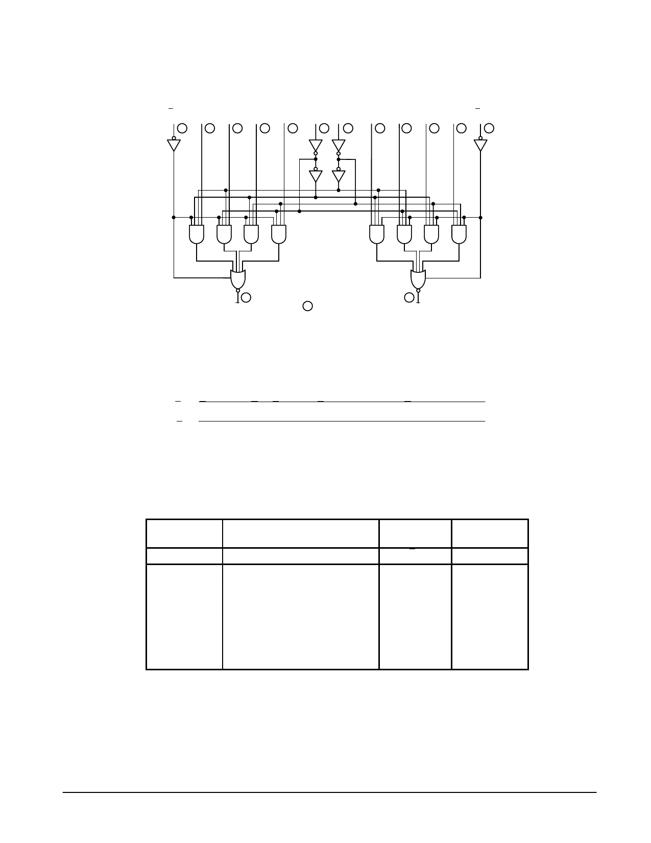
SN54 / 74LS353
LOGIC DIAGRAM
E0b
15
I3b
13
I2b
12
I1b
11
I0b
10
S0 S1
14
2
I3a
I2a I1a
I0a E0a
3
4
5
6
1
VCC = PIN 16
9
GND = PIN 8
7
Zb
= PIN NUMBERS
Za
FUNCTIONAL DESCRIPTION
The SN54 / 74LS353 contains two identical 4-input Multi-
plexers with 3-state outputs. They select two bits from four
sources selected by common select inputs (S0, S1). The
4-input multiplexers have individual Output Enable (E0a, E0b)
inputs which when HIGH, forces the outputs to a high
impedance (high Z) state.
The logic equations for the outputs are shown below:
Za = E0a • (I0a • S1 • S0 + I1a • S1 • S0 + I2a • S1 • S0 + I3a • S1 • S0)
Zb = E0b • (I0b • S1 • S0 + I1b • S1 • S0 + I2b • S1 • S0 + I3b • S1 • S0)
If the outputs of 3-state devices are tied together, all but one
device must be in the high impedance state to avoid high
currents that would exceed the maximum ratings. Designers
should ensure that Output Enable signals to 3-state devices
whose outputs are tied together are designed so that there is
no overlap.
TRUTH TABLE
SELECT
INPUTS
DATA INPUTS
S0
S1
I0
I1
I2
I3
X
X
X
X
X
X
L
L
L
X
X
X
L
L
H
X
X
X
H
L
X
L
X
X
H
L
X
H
X
X
L
H
X
X
L
X
L
H
X
X
H
X
H
H
X
X
X
L
H
H
X
X
X
H
H = HIGH Level
L = LOW Level
X = Immaterial
(Z) = High Impedance (off)
Address inputs S0 and S1 are common to both sections.
OUTPUT
ENABLE
E0
H
L
L
L
L
L
L
L
L
OUTPUT
Z
(Z)
H
L
H
L
H
L
H
L
FAST AND LS TTL DATA
5-511
Share Link: 