MX826 查看數據表(PDF) - MX-COM Inc
零件编号
产品描述 (功能)
生产厂家
MX826 Datasheet PDF : 13 Pages
| |||
AMPS/NAMPS System Audio Processor.
MX826 Preliminary Information
The Controlling System: C-BUS Hardware Interface
C-BUS is MX-COM's proprietary standard for the transmission of commands and data between a µController and MX-
COM's New Generation integrated circuits. C-BUS has been designed for a low IC pin-count, flexibility in handling variable
amounts of data, and simplicity of system design and µController software.
It may be used with any µController, and can, if desired, take advantage of the hardware serial I/O functions built into
many types of µController. Because of this flexibility and because the BUS data-rate is determined solely by the
µController, the system designer has complete freedom to choose a µController appropriate to the overall system
processing requirements.
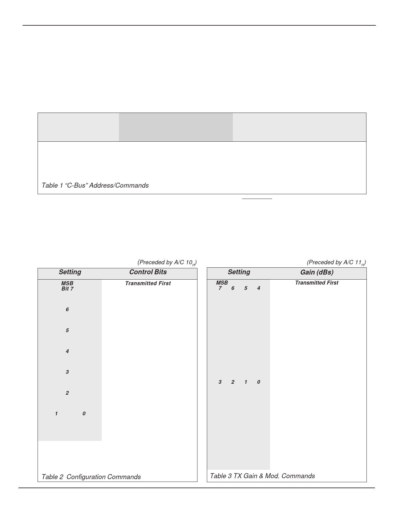
Control of the functions and levels within the MX826 is by a group of Address/Commands and appended data
instructions from the system µController to set/adjust the functions and elements of the device. The use of these
instructions is detailed in the following paragraphs and tables.
Command
Assignment
Address/Command (A/C) Byte
Hex
Binary
MSB
LSB
Command
Data
Table
General Reset
01
00000001
Configuration Command
10
00010000
TX Gain & Mod. Command
11
00010001
RX Gain & Vol. Command
12
00010010
Powersave Command
13
00010011
Table 1 “C-Bus” Address/Commands
+
1 byte
2
+
1 byte
3
+
1 byte
4
+
1 byte
5
In C-BUS protocol the audio processor is allocated
Address/Command (A/C) values 10H to 13H. Configuration, TX/
RX Gains, Powersave assignments and data requirements are
given in Table 1. Each instruction consists of an Address/
Command (A/C) byte followed by a data instruction formulated
from the following tables.
Commands and Data are only to be loaded in the group
configurations detailed, as the C-BUS interface recognizes the
first byte after Chip Select (logic “0”) as an Address/Command.
Function or Level control data, which is detailed in Tables 2, 3,
4 and 5, is acted upon at the end of the loaded instruction. See
Timing Diagrams, Figures 5 and 6.
Upon Power-Up the value of the “bits” in this device will be
random (either “0” or “1”). A General Reset Command (01H)
will be required to set all MX826 registers to 00 .
H
Configuration Command (Preceded by A/C 10 )
H
Setting
Control Bits
MSB
Bit 7
0
1
Transmitted First
Sw8 Sidetone
Sidetone Bias
Sidetone Enabled
6
Sw6/7 RX Audio
0
Ear Enabled, LS Bias
1
LS Enabled, Ear Bias
5
Sw5 Expandor
0
Expander By-Pass
1
Expander Route
4
Sw4 TX/RX Audio
0
Tx Store/Audio
1
Rx Store/Audio
3
Sw3 Dev. Limiter
0
Dev. Limiter Bypass
1
Dev. Limiter Route
2
Sw1 Mic. Inputs
0
Mic. 1 Input
1
Mic.2 Input
1
0
0
0
0
1
1
0
1
1
Sw2 TX Function
DTMF In
Compressor Bypass
Compressor In
Play In
Table 2 Configuration Commands
TX Gain & Mod. Command (Preceded by A/C 11 )
H
Setting
Gain (dBs)
MSB
7654
0000
0001
0010
0011
0100
0101
0110
0111
1000
1001
1010
1011
1100
1101
1110
1111
Transmitted First
Tx Mod. Level
OFF
(Low Z
-5.6
to
VBIAS)
-5.2
-4.8
-4.4
-4.0
-3.6
-3.2
-2.8
-2.4
-2.0
-1.6
-1.2
-0.8
-0.4
0
3210
0000
0001
0010
0011
0100
0101
0110
0111
1000
1001
1010
1011
1100
1101
1110
1111
TX Input Gain
-2.65
-2.05
-1.50
-0.95
-0.45
0
0.45
0.85
1.25
1.65
2.05
2.40
2.70
3.05
3.35
3.65
Table 3 TX Gain & Mod. Commands
© 1997 MX•COM Inc.
www.mxcom.com Tele: 800 638-5577 910 744-5050 Fax: 910 744-5054
Doc. # 20480070.004
4800 Bethania Station Road, Winston-Salem, NC 27105-1201 USA All trademarks and service marks are held by their respective companies.
Share Link: 