MLX90721S 查看數據表(PDF) - Melexis Microelectronic Systems
零件编号
产品描述 (功能)
生产厂家
MLX90721S Datasheet PDF : 11 Pages
| |||
MLX90721
Auto Shut Off Timer
General Description
The chip is intended to be used for switching on and
off a mains powered device, with the added feature
of automatic switch off after a fixed amount of time.
Such device can replace conventional switches in all
appliances that might be left on inadvertently.
Besides saving energy, the main goal is to prevent
all hazards due to appliances left on unattended.
The chip is offered in a 3-pin version, where applying
the supply is switching the chip on. In its 4-pin
version, switching on and off is done with a single
push-button.
As an alternative the fourth pin can also be used as
a reset pin, where the auto-shut-off time counter is
reset when pushing this button.
The chip application version (3 or 4 pins) and auto-
shut-off time are mask programmable. The auto-
shut-off time can be almost any value between 2.5
minutes and 32 hours. The duty cycle of the relay
driver can also be adjusted by the same mask to
adapt to all types of relay construction.
Power-On-Reset.
The Power-On-Reset of the ASIC is a combination of
a digital power-on-reset with hysteresis DPOR, and
an analog APOR.
DPOR is used to initialize the logic on the chip.
The APOR is characterized by a low level – APL
signal and a high level – APH signal, which are
debounced as follows:
low level debouncing – approx. 25mS
high level debouncing – approx. 3.5mS
The digital signal APOR is a logic combination of the
debounced signals APLd and APHd. APOR is set to
High when APHd = high and APOR is reset to Low
when APLd = low.
A transition to the active state is indicated by the
digital signal APOR=1 in case of application 1 and 2,
or APOR=1 and START=1 in case of application 3.
The result is that the transistor at the pin OUT is
activated after a delay time Td , and starts switching
ON and OFF with the specified frequency F1 and
duty cycle DC1.
The digital signal APOR=0 immediately brings the
logic back to the INACTIVE state, i.e. the output is
disabled and the state of the digital output signal
from the start-stop/reset button (if present in the
particular application) is initialized to non-pressed
(released) state.
Button Input.
The Button Input can have three different functions,
which determine the three different applications:
APPL.1, APPL.2 and APPL.3. The function of the
input is defined by the options mask.
APPL.1-No Function. The BUT input is not used
and therefore not connected externally. BUT is an
internally pulled up digital input. In this case, the
transitions INACTIVE > ACTIVE state and vice
versa are defined only by the APOR signal.
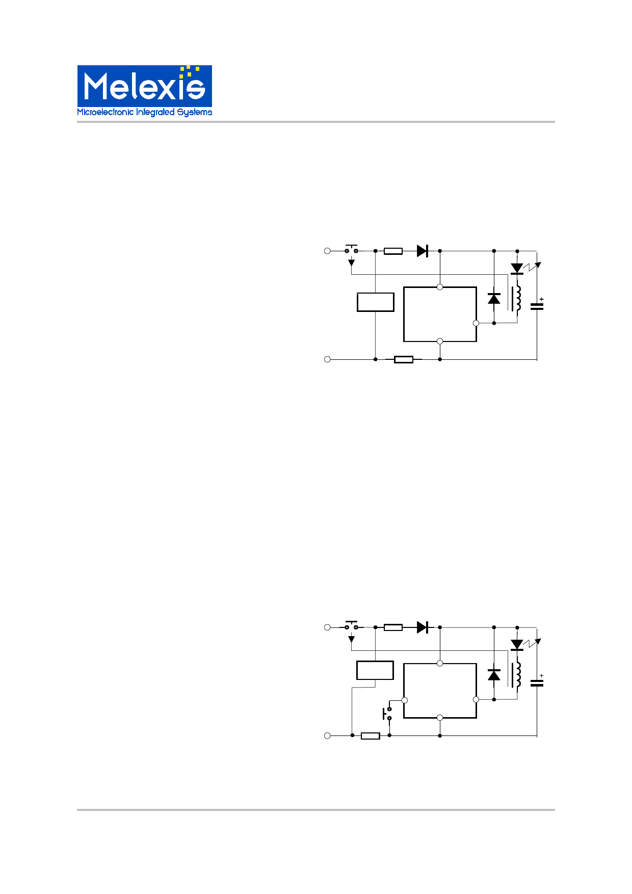
LED (optional)
L
Load
N
VDD
90721
OUT
GND
Appl.1 ASO without button
APPL.2-Auto Shut-OFF Time Reset. The input
BUT can be connected to GND via an external
button. The input is an internally pulled up, active
Low, inverting digital input. In this case, the
transitions INACTIVE state > ACTIVE state and
vice versa are again defined only by the APOR
signal. Each time the button is pressed a Reset
signal is generated and the countdown for the Auto
Shut-Off Time starts from 0 again.
The state of this input ( pressed or not ) is checked
each 3.5mS. The high level (button pressed) at the
digital output is debounced for approx. 3.5mS.
LED (optional)
L
Load
VDD
90721
BUT GND OUT
N
Appl.1 ASO with time reset button
MLX90721 Auto Shut Off Timer
Page 2
Rev 1.0 22/Jun/00
Share Link: 