STK433-730-E 查看數據表(PDF) - SANYO -> Panasonic
零件编号
产品描述 (功能)
生产厂家
STK433-730-E Datasheet PDF : 12 Pages
| |||
STK433-730-E
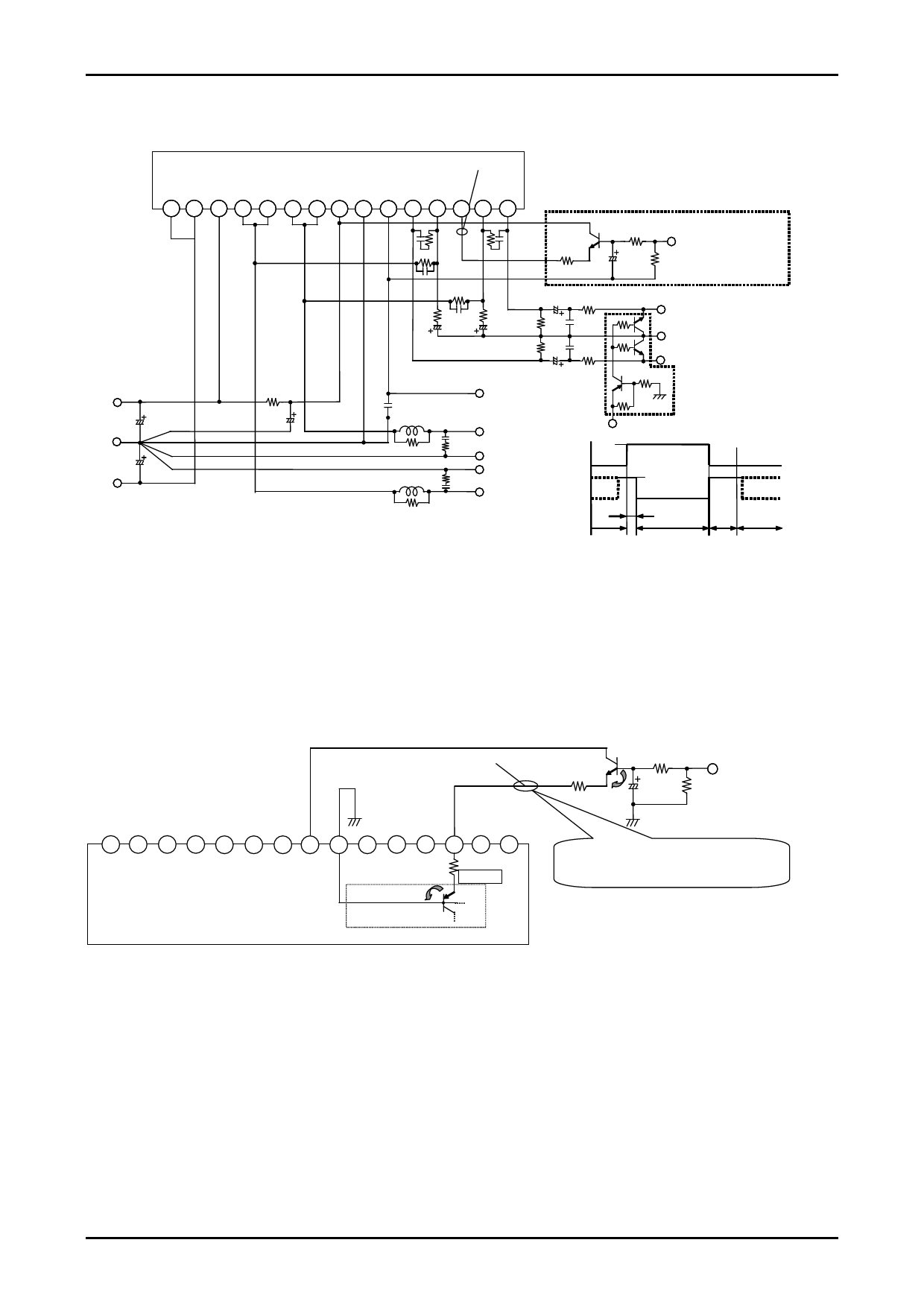
STK433-700series Stand-by Control & Mute Control Application
STK433-700series
VST
Ch1 Ch1 Ch2 Ch2
SUB/
Ch1 Ch1
Ch2 Ch2
-PRE -VCC +VCC OUT OUT OUT OUT +PRE GND MONITOR IN NF ST-BY NF IN
1 2 3 4 5 6 7 8 9 10 11 12 13 14 15
1kΩ
33kΩ
33μF
Stand-by Control(ex)
H: Operation Mode(+5V)
L: Stand-by Mode(0V)
2kΩ
+VCC
GND
-VCC
MONITOR
Ch2 OUT
GND
GND
Ch1 OUT
Stand-by
Control
Mute
Control
Ch2 IN
10kΩ
GND
10kΩ
10kΩ
Ch1 IN
2.2kΩ
Mute Control
H: Single Mute
L: Normal
+5V
+5V
MUTE
ST-BY
PLAY
MUTE ST-BY
[The example of use STK433-*00series Stand-by control circuit]
Features
• By using the recommended stand-by control application, the pop noise level when the power is turned on/off can be
significantly reduced.
• By adjusting the limiting resistance (*1) in accordance with the voltages of the microcontroller and other components
used, it is possible to perform stand-by control, facilitating the finished product design effort.
(ex) STK433-*00series test circuit. When impressed by Stand-by control control [+5V].
Stand-by control circuit part
H: Operation mode (+5V)
VST
33kΩ
L: Stand-by mode (0V)
1kΩ (*1)
33μF (min) 2kΩ
ΔVBE (*3)
(*4)
12
3
-PRE -VCC +VCC
4
Ch1
OUT
5
Ch1
OUT
6
Ch2
OUT
7 8 9 10 11
Ch2 +PRE SUB/ MONITOR Ch1
OUT
GND
IN
12 13 14 15
Ch1 ST-BY
Ch2 Ch2
NF
NF IN
4.3kΩ (*2)
ΔVBE
STK433-*00series
Stand-by Circuit
in Pre Driver IC
ex) VST=(Stand-by Control-VBE*2)× (*2)/((*1)+(*2))+VBE
=(5V-0.6V*2)×4.3kΩ/(4.3kΩ+1kΩ)+0.6V
≈3.68(V)
Operation Explanation
1) About VST (#13pin Stand-by Threshold)
<1> Operation Mode
When pin 13 reference voltage VST is equal to or greater than 2.5 V, the stand-by circuit is set off, and the
amplifier is set to the operation mode.
<2> Stand-by Mode
When pin 13 reference voltage VST is equal to or less than 0.6V, the stand-by circuit is set off, and the amplifier is
set to the stand-by mode.
(*3) The pop noise that occurs when the power is turned ON is reduced by providing a time constant using a capacitor
during operation.
(*4) The pop noise level is reduced by discharging the capacitor with a resistor in the stand-by mode.
No. A1249-11/12
Share Link: 