STM1817T 查看數據表(PDF) - STMicroelectronics
零件编号
产品描述 (功能)
生产厂家
STM1817T Datasheet PDF : 25 Pages
| |||
Operation
STM1810/1811/1812/1813/1815/1816/1817/1818
threshold and lasts 20 µs or less will not cause a reset pulse. A 0.1 µF bypass capacitor
mounted as close as possible to the VCC pin provides additional transient immunity.
2.5
Note:
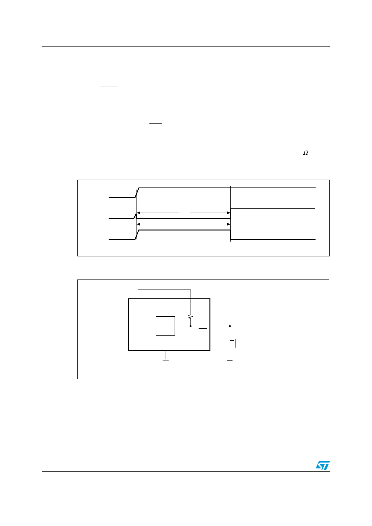
Valid RST output down to VCC = 0 V
When VCC falls below 1 V, the RST output no longer sinks current, but becomes an open
circuit. In most systems this is not a problem, as most MCUs do not operate below 1 V.
However, in applications where RST output must be valid down to 0 V, a pull-down resistor
may be added to hold the RST output low (see Figure 12). This resistor must be large
enough to not load the RST output, and still be small enough to pull the output to ground. A
100 kΩ resistor is recommended.
The same situation applies for the active-high RST of the STM1810/1812. A 100 kΩ pull-up
resistor to VCC should be used if RST must remain valid for VCC < 1.0 V.
Figure 8. Reset timing diagram
VCC
VRST
RST VCC (min)
trec
trec
RST(1)
AI09653
1. RST for STM1812 and STM1817.
Figure 9. Push-button manual reset with MR detect (STM1813/1818)
VCC
STM1813
STM1818
Reset
Monitor
VCC
5.5 kΩ
RST
VSS
Micro RESET
Push-button RESET
AI09654
10/25
Share Link: 