STV6415AB жҹҘзңӢж•ёж“ҡиЎЁпјҲPDFпјү - STMicroelectronics
йӣ¶д»¶зј–еҸ·
дә§е“ҒжҸҸиҝ° (еҠҹиғҪ)
з”ҹдә§еҺӮ家
STV6415AB Datasheet PDF : 15 Pages
| |||
General description
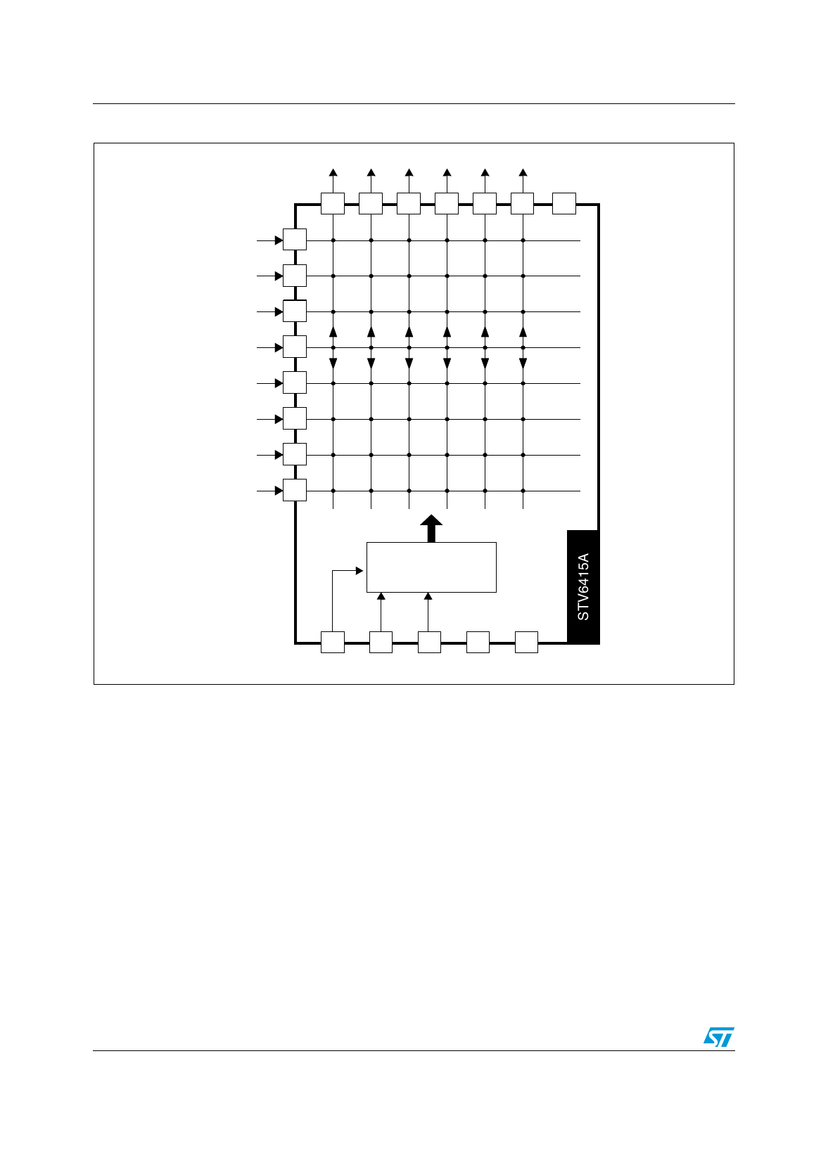
Figure 2.
STV6415A block diagram
Output Output Output Output Output Output
Ground
18 17 16 15 14 13 12
Input
1
Input
3
Input
5
Input
6
Input
8
Input
10
Input
11
Input
20
STV6415A
Bus Decoder
2
Data
7
Prog
4
9
19
Clock VCC Ground
The main function of the STV6415A is to switch eight video input sources on the six outputs.
Each output can be switched to only one of the inputs, whereas any single input may be
connected to several outputs. The lowest level of each signal is aligned on each input
(bottom of sync pulse for CVBS or Black Level for RGB signals).
The nominal gain between any input and output is 6.5 dB. For Chroma signals, the
alignment is switched off by forcing, with an external 5 VDC resistor bridge on the input.
Each input can be used as a normal input or as a Chroma input (with external resistor
bridge). All the switching possibilities are changed through the IВІC bus.
Driving a 75 О© load requires an external transistor.
The switch configuration is defined by words of 16 bits: the IВІC address (8 bits) then one
output configuration (8 bits). Therefore, six separated words of 16 bits are necessary to
determine the starting configuration at power-on (power supply: 0 to 10 V).
A new configuration needs only the words (16 bits) of the changed output channels.
4/15
Share Link: 