STV6415A жҹҘзңӢж•ёж“ҡиЎЁпјҲPDFпјү - STMicroelectronics
йӣ¶д»¶зј–еҸ·
дә§е“ҒжҸҸиҝ° (еҠҹиғҪ)
з”ҹдә§еҺӮ家
STV6415A Datasheet PDF : 15 Pages
| |||
STV6415A
Electrical characteristics
Table 4. IВІC bus characteristics (continued)
Symbol
Parameter
Test conditions
tBUF
tHD, STA
tSU, STA
Start set-up time following a stop
Start hold time
Start set-up time following clock low-to-high transition
Min.
4.7
4.0
4.7
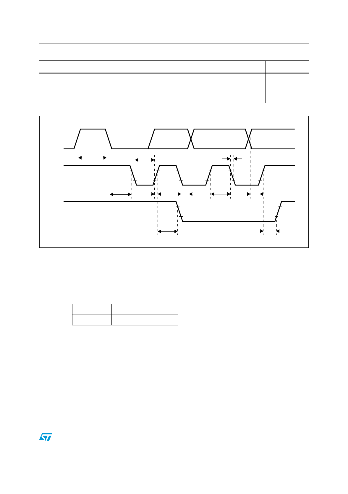
Figure 3. IВІC bus timing
Max. Unit
Вөs
Вөs
Вөs
SDA
SCL
tBUF
tLOW
tHD,STA
tR
SDA
(start, stop)
tSU,STA
tF
tHD,DAT tHIGH
tSU,DAT
tSU,STO
2.5
IВІC bus selections
The IВІC chip address is defined by the first byte. The second and following bytes define the
input/output configurations.
Table 5.
0x86
0x06
First byte (address)
0b1000 0110
0b0000 0110
When PROG pin is connected to Ground
When PROG pin is connected to VCC
7/15
Share Link: 