UM110N04-2M1P-E3(Rev_A) 查看數據表(PDF) - Vishay Semiconductors
零件编号
产品描述 (功能)
生产厂家
UM110N04-2M1P-E3 Datasheet PDF : 8 Pages
| |||
New Product
SUM110N04-2m1P
Vishay Siliconix
N-Channel 40-V (D-S) MOSFET
PRODUCT SUMMARY
VDS (V)
RDS(on) (Ω)
40
0.0021 at VGS = 10 V
0.0024 at VGS = 4.5 V
ID (A)a, c
110
110
Qg (Typ.)
240 nC
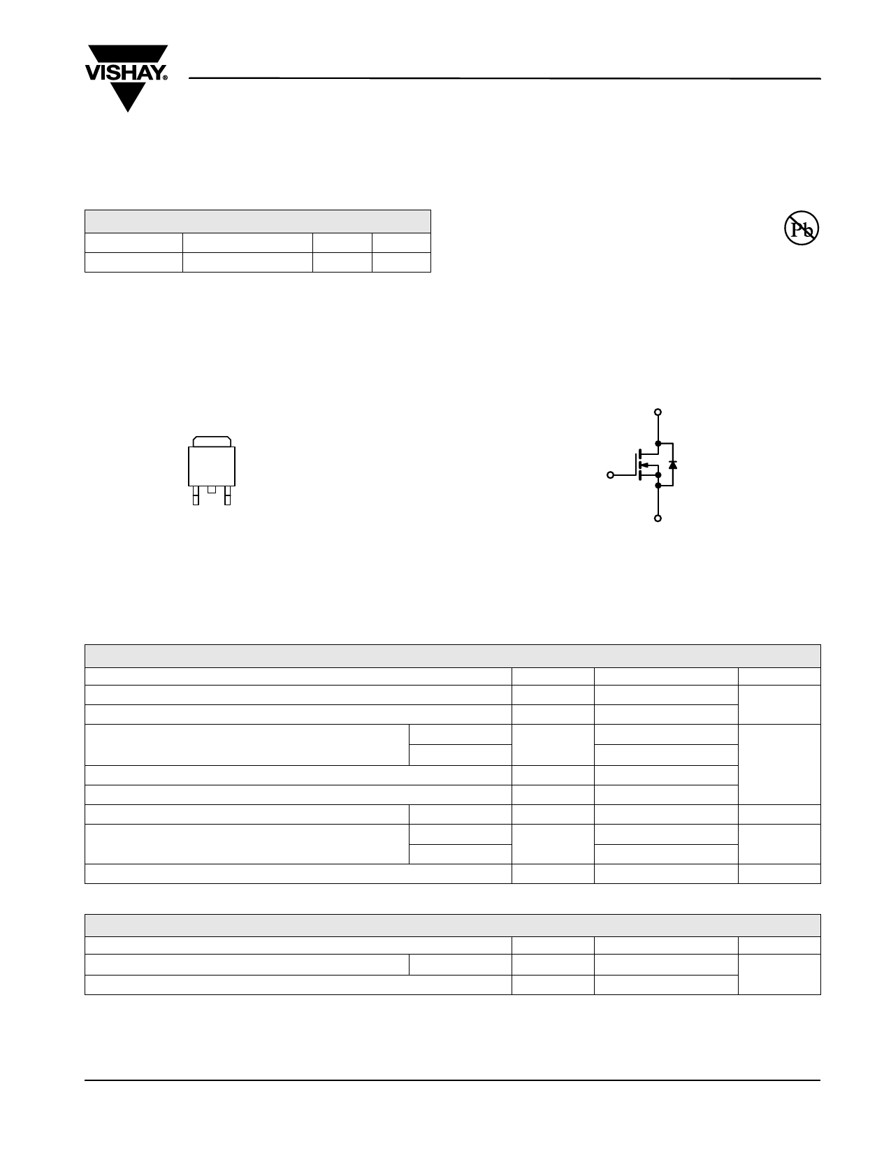
TO-263
FEATURES
• TrenchFET® Power MOSFET
• 100 % Rg and UIS Tested
APPLICATIONS
• Synchronous Rectification
• Power Supplies
D
RoHS
COMPLIANT
G
G DS
Top View
Ordering Information: SUM110N04-2m1P-E3 (Lead (Pb)-free)
S
N-Channel MOSFET
ABSOLUTE MAXIMUM RATINGS TA = 25 °C, unless otherwise noted
Parameter
Symbol
Drain-Source Voltage
VDS
Gate-Source Voltage
VGS
TC = 25 °C
Continuous Drain Current (TJ = 175 °C)
TC = 70 °C
TA = 25 °C
ID
TA = 70 °C
Pulsed Drain Current
IDM
Avalanche Current Pulse
Single Pulse Avalanche Energy
L = 0.1 mH
IAS
EAS
Continuous Source-Drain Diode Current
TC = 25 °C
TA = 25 °C
IS
TC = 25 °C
Maximum Power Dissipation
TC = 70 °C
TA = 25 °C
PD
TA = 70 °C
Operating Junction and Storage Temperature Range
TJ, Tstg
Limit
40
± 20
110a, c
110c
29b
23b
250
80
320
110a, c
2.6b
312a
200
3.13b
2.0b
- 55 to 150
THERMAL RESISTANCE RATINGS
Parameter
Symbol
Maximum Junction-to-Ambientb
Steady State
RthJA
Maximum Junction-to-Case
Steady State
RthJC
Notes:
a. Based on TC = 25 °C.
b. Surface Mounted on 1" x 1" FR4 board.
c. Calculated based on maximum junction temperature. Package limitation current is 110 A.
Typical
32
0.33
Maximum
40
0.4
Unit
V
A
V
A
W
°C
Unit
°C/W
Document Number: 69983
S-80680-Rev. A, 31-Mar-08
www.vishay.com
1
Share Link: 