TC7652 查看數據表(PDF) - Microchip Technology
零件编号
产品描述 (功能)
生产厂家
TC7652 Datasheet PDF : 16 Pages
| |||
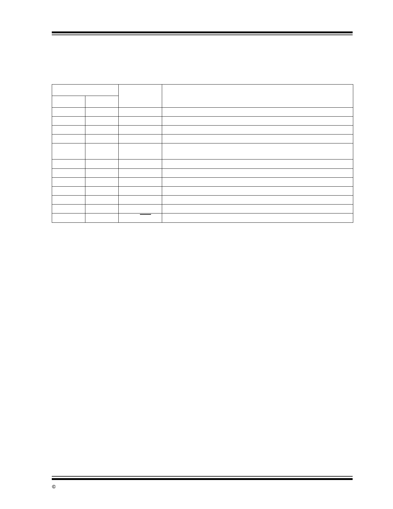
2.0 PIN DESCRIPTIONS
The descriptions of the pins are listed in Table 2-1.
TABLE 2-1: PIN FUNCTION TABLE
Pin Number
8-pin DIP 14-pin DIP
Symbol
Description
1,8
2,1
CA, CB
Nulling capacitor pins
2
4
-INPUT Inverting Input
3
5
+INPUT Non-inverting Input
4
7
VSS
Negative Power Supply
5
9
OUTPUT Output Voltage Clamp
CLAMP
6
10
OUTPUT Output
7
11
—
3,6
VDD
Positive Power Supply
NC
No internal connection
—
8
CRETN
Capacitor current return pin
—
12
INT CLK OUT Internal Clock Output
—
13
EXT CLK IN External Clock Input
—
14
INT/EXT Select Internal or External Clock
TC7652
© 2002 Microchip Technology Inc.
DS21464B-page 5
Share Link: 