EN80C196NT 查看數據表(PDF) - Intel
零件编号
产品描述 (功能)
生产厂家
EN80C196NT Datasheet PDF : 31 Pages
| |||
8XC196NT
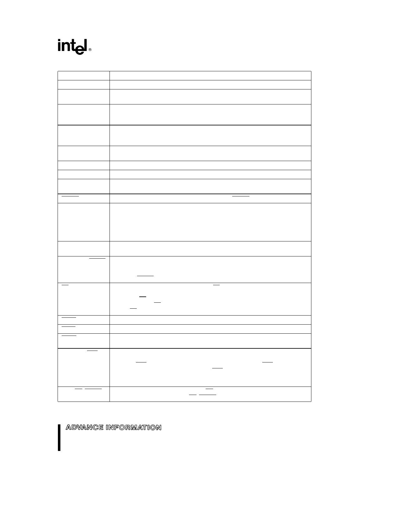
PIN DESCRIPTIONS
Symbol
Name and Function
VCC
VSS VSS1 VSS1
Main supply voltage (a5V)
Digital circuit ground (0V) There are multiple VSS pins all of which MUST be
connected
VREF
Reference for the A D converter (a5V) VREF is also the supply voltage to the
analog portion of the A D converter and the logic used to read Port 0 Must be
connected for A D and Port 0 to function
VPP
Programming voltage for the OTPROM parts It should be a12 5V for programming
It is also the timing pin for the return from powerdown circuit Connect to VCC if
powerdown not being used
ANGND
XTAL1
Reference ground for the A D converter Must be held at nominally the same
potential as VSS
Input of the oscillator inverter and the internal clock generator
XTAL2
Output of the oscillator inverter
P2 7 CLKOUT
Output of the internal clock generator The frequency is the oscillator frequency
It has a 50% duty cycle Also LSIO pin
RESET
Reset input to and open-drain output from the chip RESET has an internal pullup
P5 7 BUSWIDTH
Input for bus width selection If CCR bit 1 is a one and CCR1 bit 2 is a one this pin
dyamically controls the Buswidth of the bus cycle in progress If BUSWIDTH is low
an 8-bit cycle occurs if BUSWIDTH is high a 16-bit cycle occurs If CCR bit 1 is ‘‘0’’
and CCR1 bit 2 is ‘‘1’’ all bus cycles are 8-bit if CCR bit 1 is ‘‘1’’ and CCR1 bit 2 is
‘‘0’’ all bus cycles are 16-bit CCR bit 1 e ‘‘0’’ and CCR1 bit 2 e ‘‘0’’ is illegal Also
an LSIO pin when not used as BUSWIDTH
NMI
A positive transition causes a non maskable interrupt vector through memory
location 203EH
P5 1 INST SLPCS
Output high during an external memory read indicates the read is an instruction
fetch INST is valid throughout the bus cycle INST is active only during external
memory fetches during internal OTPROM fetches INST is held low Also LSIO when
not INST SLPCS is the Slave Port Chip Select
EA
Input for memory select (External Access) EA equal to a high causes memory
accesses to locations 0FF2000H through 0FF9FFFH to be directed to on-chip
OTPROM EA equal to a low causes accesses to these locations to be directed to
off-chip memory EA e a12 5V causes execution to begin in the Programming
Mode EA is latched at reset
HOLD
Bus Hold Input requesting control of the bus
HLDA
Bus Hold acknowledge output indicating release of the bus
BREQ
Bus Request output activated when the bus controller has a pending external
memory cycle
P5 0 ALE ADV
SLPADDR
SLPALE
Address Latch Enable or Address Valid output as selected by CCR Both pin
options provide a latch to demultiplex the address from the address data bus When
the pin is ADV it goes inactive (high) at the end of the bus cycle ADV can be used
as a chip select for external memory ALE ADV is active only during external
memory accesses Also LSIO when not used as ALE SLPADDR is the Slave Port
Address Control Input and SLPALE is the Slave Port Address Latch Enable Input
P5 3 RD SLPRD
Read signal output to external memory RD is active only during external memory
reads or LSIO when not used as RD SLPRD is the Slave Port Read Control Input
5
Share Link: 