LP87C51-2 查看數據表(PDF) - Intel
零件编号
产品描述 (功能)
生产厂家
LP87C51-2 Datasheet PDF : 21 Pages
| |||
87C51 80C51BH 80C31BH
In normal operation ALE is emitted at a constant
rate of 1 6 the oscillator frequency and may be
used for external timing or clocking purposes Note
however that one ALE pulse is skipped during each
access to external Data Memory
PSEN Program Store Enable is the Read strobe to
External Program Memory When the 87C51 BH is
executing from Internal Program Memory PSEN is
inactive (high) When the device is executing code
from External Program Memory PSEN is activated
twice each machine cycle except that two PSEN
activations are skipped during each access to Exter-
nal Data Memory
EA VPP External Access enable EA must be
strapped to VSS in order to enable the 87C51 BH to
fetch code from External Program Memory locations
starting at 0000H up to FFFFH Note however that
if either of the Lock Bits is programmed the logic
level at EA is internally latched during reset
EA must be strapped to VCC for internal program
execution
This pin also receives the programming supply volt-
age (VPP) during EPROM programming
XTAL1 Input to the inverting oscillator amplifier
XTAL2 Output from the inverting oscillator amplifi-
er
OSCILLATOR CHARACTERISTICS
XTAL1 and XTAL2 are the input and output respec-
tively of an inverting amplifier which can be config-
ured for use as an on-chip oscillator as shown in
Figure 3
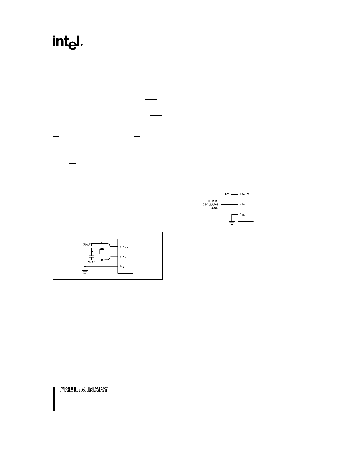
To drive the device from an external clock source
XTAL1 should be driven while XTAL2 is left uncon-
nected as shown in Figure 4 There are no require-
ments on the duty cycle of the external clock signal
since the input to the internal clocking circuitry is
through a divide-by-two flip-flop but minimum and
maximum high and low times specified on the data
sheet must be observed
An external oscillator may encounter as much as a
100 pF load at XTAL1 when it starts up This is due
to interaction between the amplifier and its feedback
capacitance Once the external signal meets the VIL
and VIH specifications the capacitance will not ex-
ceed 20 pF
272335 – 6
Figure 4 External Clock Drive
272335 – 5
Figure 3 Using the On-Chip Oscillator
5
Share Link: 