A3240EUA-TL 查看數據表(PDF) - Allegro MicroSystems
零件编号
产品描述 (功能)
生产厂家
A3240EUA-TL Datasheet PDF : 12 Pages
| |||
3240
CHOPPER-STABILIZED,
PRECISION
HALL-EFFECT SWITCH
FUNCTIONAL DESCRIPTION
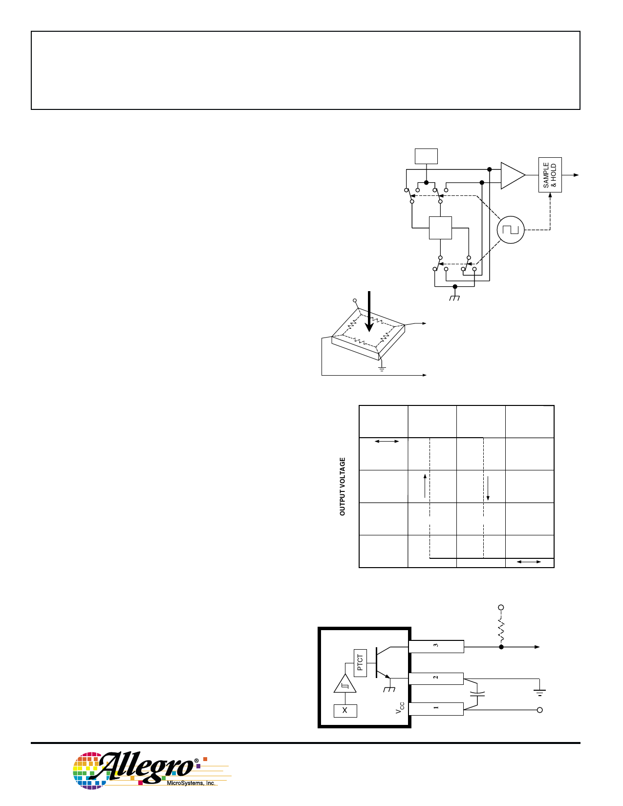
Chopper-Stabilized Technique. The Hall element can be
considered as a resistor array similar to a Wheatstone bridge. A
large portion of the offset is a result of the mismatching of these
resistors. These devices use a proprietary dynamic offset
cancellation technique, with an internal high-frequency clock to
reduce the residual offset voltage of the Hall element that is
normally caused by device overmolding, temperature dependen-
cies, and thermal stress. The chopper-stabilizing technique
cancels the mismatching of the resistor circuit by changing the
direction of the current flowing through the Hall plate using
CMOS switches and Hall voltage measurement taps, while
maintaing the Hall-voltage signal that is induced by the external
magnetic flux. The signal is then captured by a sample-and-
hold circuit and further processed using low-offset bipolar
circuitry. This technique produces devices that have an
extremely stable quiescent Hall output voltage, are immune to
thermal stress, and have precise recoverability after temperature
cycling. This technique will also slightly degrade the device
output repeatability. A relatively high sampling frequency is
used in order that faster signals can be processed.
More detailed descriptions of the circuit operation can be
found in: Technical Paper STP 97-10, Monolithic Magnetic
Hall Sensor Using Dynamic Quadrature Offset Cancellation
and Technical Paper STP 99-1, Chopper-Stabilized Amplifiers
With A Track-and-Hold Signal Demodulator.
Operation. The output of these devices switches low (turns
on) when a magnetic field perpendicular to the Hall sensor
exceeds the operate point threshold (BOP). After turn-on, the
output is capable of sinking 25 mA and the output voltage is
VOUT(SAT). Note that the device latches; that is, a south pole of
sufficient strength towards the branded surface of the device
will turn the device on; removal of the south pole will leave the
device on. When the magnetic field is reduced below the
release point (BRP), the device output goes high (turns off). The
difference in the magnetic operate and release points is the
hysteresis (Bhys) of the device. This built-in hysteresis allows
clean switching of the output even in the presence of external
mechanical vibration and electrical noise.
Applications. It is strongly recommended that an external
bypass capacitor be connected (in close proximity to the Hall
sensor) between the supply and ground of the device to reduce
both external noise and noise generated by the chopper-
stabilization technique.
The simplest form of magnet that will operate these devices
is a ring magnet. Other methods of operation, such as linear
magnets, are possible. Extensive applications information on
magnets and Hall-effect sensors is also available in the Allegro
Electronic Data Book AMS-702 or Application Note 27701, or
www.allegromicro.com
B
+V
+V
VCC
0
0
REG
X
—
HALL
VOLTAGE
+
Dwg. AH-011-2
Dwg. EH-012
B RP
B OP
FLUX DENSITY
VOUT(SAT)
+B
Dwg. GH-007-2
SUPPLY
OUTPUT
0.1 µF
SUPPLY
Dwg. EH-013
115 Northeast Cutoff, Box 15036
8
Worcester, Massachusetts 01615-0036 (508) 853-5000
Share Link: 