ICL7650CPA 查看數據表(PDF) - Linear Technology
零件编号
产品描述 (功能)
生产厂家
ICL7650CPA Datasheet PDF : 24 Pages
| |||
LTC1052/LTC7652
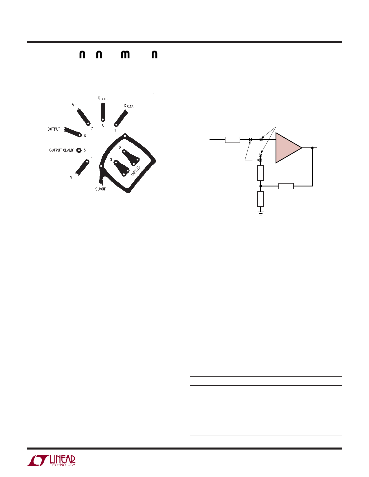
APPLICATIO S I FOR ATIO
connections, to the inverting input. Guarding both sides
of the printed circuit board is required. Bulk leakage
reduction depends on the guard ring width.
Figure 2 is an example of the introduction of an
unnecessary resistor to promote differential thermal
balance. Maintaining compensating junctions in close
physical proximity will keep them at the same temperature
and reduce thermal EMF errors.
NOMINALLY UNNECESSARY
RESISTOR USED TO
THERMALLY BALANCE OTHER
INPUT RESISTOR
RESISTOR LEAD, SOLDER,
COPPER TRACE JUNCTION
LEAD WIRE/SOLDER/COPPER
TRACE JUNCTION
+
LTC1052
–
OUTPUT
Microvolts
Thermocouple effects must be considered if the LTC1052’s
ultralow drift is to be fully utilized. Any connection
of dissimilar metals forms a thermoelectric junction
producing an electric potential which varies with
temperature (Seebeck effect). As temperature sensors,
thermocouples exploit this phenomenon to produce
useful information. In low drift amplifier circuits the effect
is a primary source of error.
Connectors, switches, relay contacts, sockets, resistors,
solder, and even copper wire are all candidates for
thermal EMF generation. Junctions of copper wire from
different manufacturers can generate thermal EMFs of
200nV/°C—4 times the maximum drift specification of
the LTC1052. The copper/kovar junction, formed when
wire or printed circuit traces contact a package lead, has
a thermal EMF of approximately 35µV/°C– 700 times the
maximum drift specification of the LTC1052.
Minimizing thermal EMF-induced errors is possible if
judicious attention is given to circuit board layout and
component selection. It is good practice to minimize the
number of junctions in the amplifier’s input signal path.
Avoid connectors, sockets, switches and relays where
possible. In instances where this is not possible, attempt
to balance the number and type of junctions so that
differential cancellation occurs. Doing this may involve
deliberately introducing junctions to offset unavoidable
junctions.
Figure 2
LTC1052/7652 • AI03
When connectors, switches, relays and/or sockets are
necessary they should be selected for low thermal EMF
activity. The same techniques of thermally balancing and
coupling the matching junctions are effective in reducing
the thermal EMF errors of these components.
Resistors are another source of thermal EMF errors.
Table 1 shows the thermal EMF generated for different
resistors. The temperature gradient across the resistor is
important, not the ambient temperature. There are two
junctions formed at each end of the resistor and if these
junctions are at the same temperature, their thermal EMFs
will cancel each other. The thermal EMF numbers are
approximate and vary with resistor value. High values give
higher thermal EMF.
Table 1. Resistor Thermal EMF
RESISTOR TYPE
Tin Oxide
Carbon Composition
Metal Film
Wire Wound
Evenohm
Manganin
THERMAL EMF/°C GRADIENT
~mV/’C
~450µV/°C
~20µV/°C
~2µV/°C
~2µV/°C
1052fa
9
Share Link: 