TK15404 查看數據表(PDF) - Toko America Inc
零件编号
产品描述 (功能)
生产厂家
TK15404 Datasheet PDF : 8 Pages
| |||
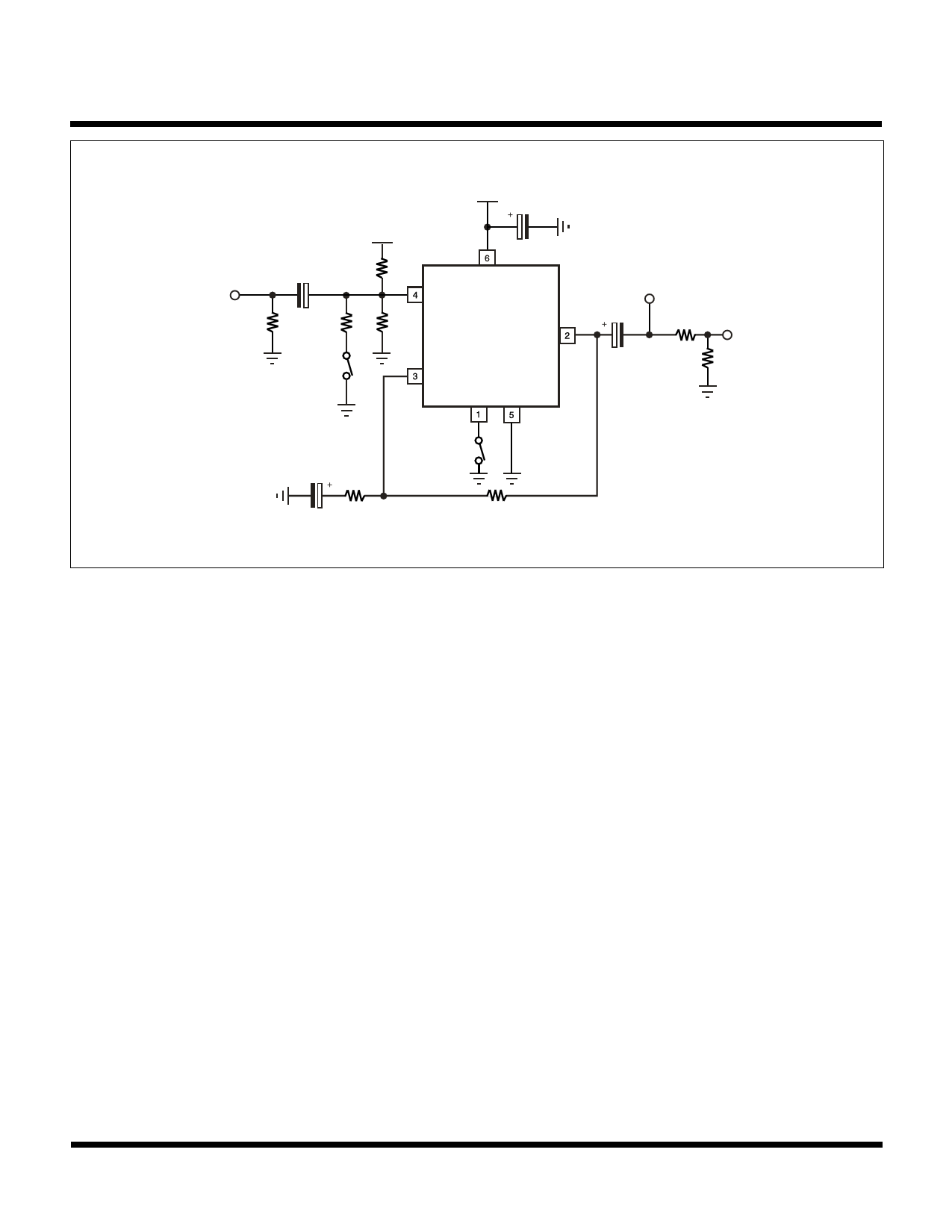
TP1
75 Ω
TEST CIRCUIT
VCC
VCC
VCC = 5.0 V
4.7 µF
+
+Input
10 kΩ
33 µF
20 kΩ
10 kΩ
SW1 is turned on SW1
only when DG and
DP are measured.
-Input
Standby
GND
2 kΩ
47 µF
2 kΩ
TK15404
TP2
Output
VOUT = 2.0 VP-P
+
75 Ω
TP3
47 µF
75 Ω
MEASUREMENT METHOD
1. Supply Current (ICC)
The Pin 6 current is measured with no input signal and the Standby Pin (Pin 1) open.
2. Standby Supply Current (ISTBY)
The Pin 6 current is measured when the Standby Pin (Pin 1) is connected to ground.
3. Standby Terminal Current (IOS)
The Pin 1 current is measured when Pin 1 is connected to ground.
4. Threshold Voltage (High to Low) (VTHL)
The Pin 1 voltage is measured at the point which changes the device from operating mode into standby mode.
5. Threshold Voltage (Low to High) (VTLH)
The Pin 1 voltage is measured at the point which changes the device from standby mode into operating mode.
6. Voltage Gain (GVA)
The voltage gain equation is as follows:
GVA = 20 log10 V2/V1
Where V1 is the input voltage at TP1 and V2 is the measured output voltage at TP2.
7. Frequency Response (fr)
The frequency response equation is as follows:
fr = 20 log V2/V1
10
Where V1 is the measured TP3 voltage when the TP1 input frequency is set to 1 MHz and V2 is the measured TP3 voltage
when the TP1 input frequency is set to 5 MHz. Furthermore, V1 is the measured TP3 voltage when the TP1 input frequency
is set to 1 MHz and V2 is the measured TP3 voltage when the TP1 input frequency is set to 10 MHz.
January 2000 TOKO, Inc.
Page 3
Share Link: 