TK15404 查看數據表(PDF) - Toko America Inc
零件编号
产品描述 (功能)
生产厂家
TK15404 Datasheet PDF : 8 Pages
| |||
TK15404
MEASUREMENT METHOD
8. Total Harmonic Distortion (THD)
The TP3 signal is measured when a 1 kHz 1 VP-P input signal is applied to TP1.
9. Maximum Output Voltage (VOUT(MAX))
A 1 kHz input signal is applied to TP1 and the amplitude is slowly increased. The output voltage at TP2 is measured at
the point the THD reaches 10%.
10. Signal to Noise Ratio (S/N)
The signal to noise ratio is measured at TP3 when a pedestal input signal is applied to TP1.
11. Differential Gain (DG)
SW1 is closed to change the input bias voltage.
The differential gain is measured at TP3 when a staircase waveform of 10 steps is applied to TP1.
12. Differential Phase (DP)
SW1 is closed to change the input bias voltage.
The differential phase is measured at TP3 when a staircase waveform of 10 steps is applied to TP1.
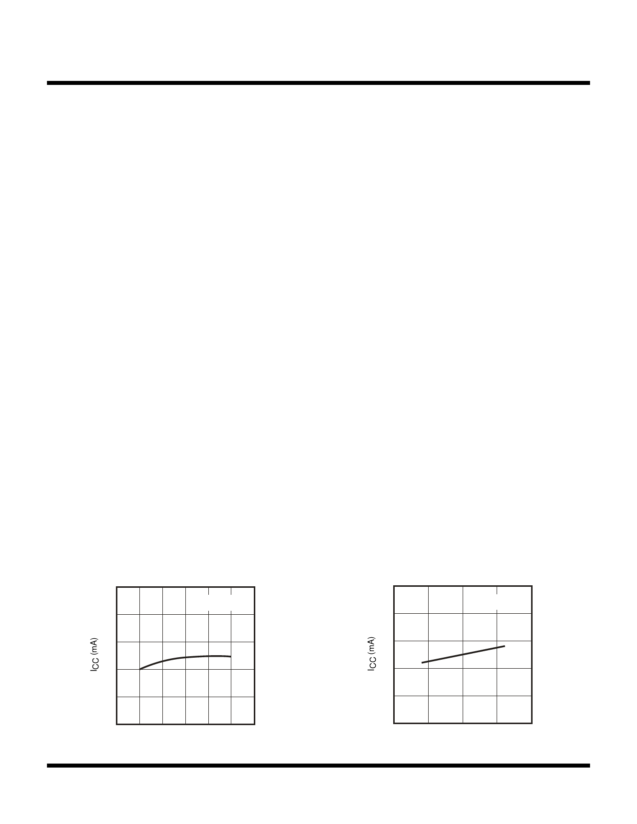
TYPICAL PERFORMANCE CHARACTERISTICS
Page 4
SUPPLY CURRENT VS.
TEMPERATURE
9
VCC = 5.0 V,
No Input
8
7
6
5
4
-50
0
50
100
TA (°C)
SUPPLY CURRENT VS.
SUPPLY VOLTAGE
9
TA = 25 °C,
No Input
8
7
6
5
4
4.0
4.5
5.0
5.5 6.0
VCC (V)
January 2000 TOKO, Inc.
Share Link: 