LH540204 жҹҘзңӢж•ёж“ҡиЎЁпјҲPDFпјү - Sharp Electronics
йӣ¶д»¶зј–еҸ·
дә§е“ҒжҸҸиҝ° (еҠҹиғҪ)
з”ҹдә§еҺӮ家
LH540204 Datasheet PDF : 18 Pages
| |||
CMOS 4096 Г— 9 Asynchronous FIFO
LH540204
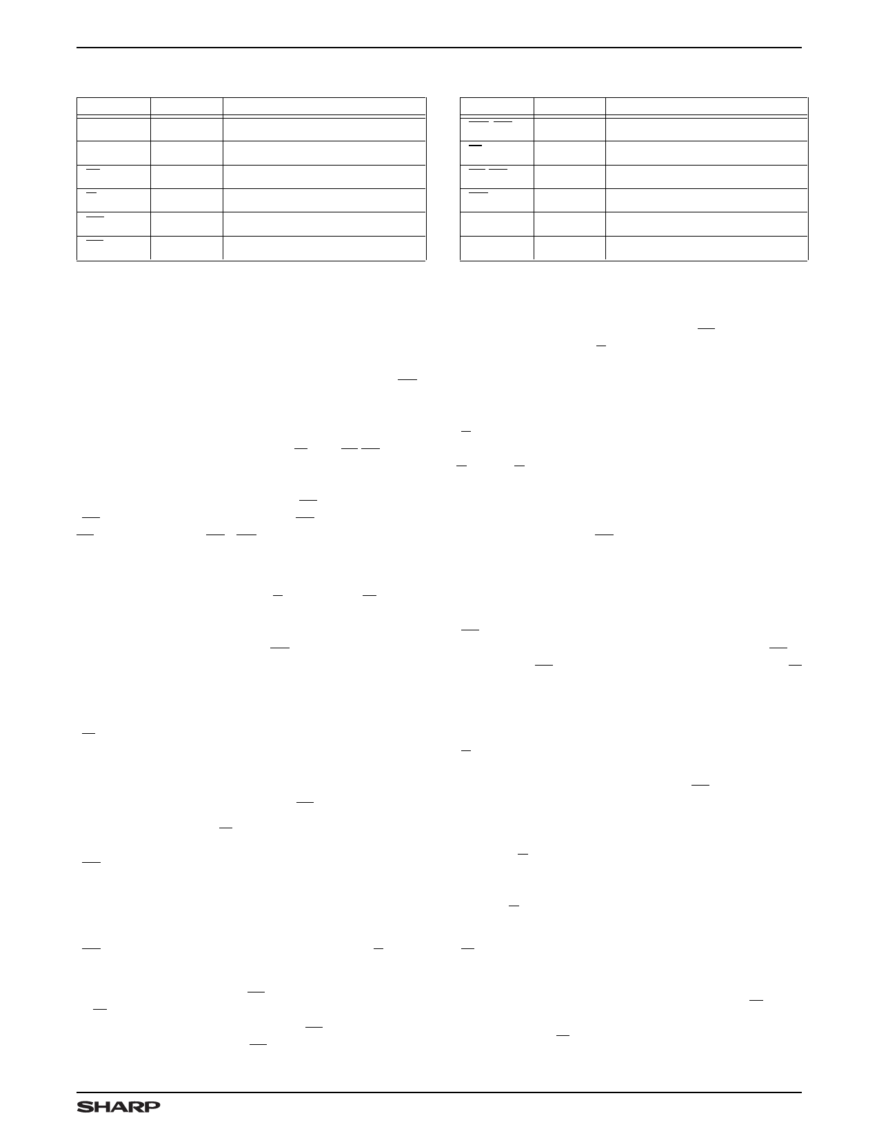
PIN DESCRIPTIONS
PIN
PIN TYPE 1
DESCRIPTION
D0 вҖ“ D8
Q0 вҖ“ Q8
W
I
Input Data Bus
O/Z Output Data Bus
I
Write Request
R
I
Read Request
EF
O
Empty Flag
FF
O
Full Flag
NOTE:
1. I = Input, O = Output, Z = High-Impedance, V = Power Voltage Level
PIN
XO/HF
XI
FL/RT
RS
VCC
VSS
PIN TYPE 1
DESCRIPTION
O
Expansion Out/Half-Full Flag
I
Expansion In
I
First Load/Retransmit
I
Reset
V
Positive Power Supply
V
Ground
OPERATIONAL DESCRIPTION
Reset
The LH540204 is reset whenever the Reset input (RS)
is taken LOW. A reset operation initializes both the read-
address pointer and the write-address pointer to point to
location zero, the first physical memory location. During
a reset operation, the state of the XI and FL/RT inputs
determines whether the device is in standalone mode or
in depth-cascaded mode. (See Tables 1 and 2.) The reset
operation forces the Empty Flag EF to be asserted
(EF = LOW), and the Half-Full Flag HF and the Full Flag
FF to be deasserted (HF = FF = HIGH); the Data Out pins
(D0 вҖ“ D8) are forced into a high-impedance state.
A reset operation is required whenever the LH540204
first is powered up. The Read (R) and Write (W) inputs
may be in any state when the reset operation is initiated;
but they must be HIGH, before the reset operation is
terminated by a rising edge of RS, by a time tRRSS (for
Read) or tWRSS (for Write) respectively. (See Figure 10.)
Write
A write cycle is initiated by a falling edge of the Write
(W) control input. Data setup times and hold times must
be observed for the data inputs (D0 вҖ“ D8). Write opera-
tions may occur independently of any ongoing read op-
erations. However, a write operation is possible only if the
FIFO is not full, (i.e., if the Full Flag FF is HIGH).
At the falling edge of W for the first write operation after
the memory is half filled, the Half-Full Flag is asserted
(HF = LOW). It remains asserted until the difference
between the write pointer and the read pointer indicates
that the data words remaining in the LH540204 are filling
the FIFO memory to less than or equal to one-half of its
total capacity. The Half-Full Flag is deasserted
(HF = HIGH) by the appropriate rising edge of R. (See
Table 3.)
The Full Flag is asserted (FF = LOW)at the falling edge
of W for the write operation which fills the last available
location in the FIFO memory array. FF = LOW inhibits
further write operations until FF is cleared by a valid read
operation. The Full Flag is deasserted (FF = HIGH) after
the next rising edge of R releases another memory loca-
tion. (See Table 3.)
Read
A read cycle is initiated by a falling edge of the Read
(R) control input. Read data becomes valid at the data
outputs (Q0 вҖ“ Q8) after a time tA from the falling edge of
R. After R goes HIGH, the data outputs return to a
high-impedance state. Read operations may occur inde-
pendently of any ongoing write operations. However, a
read operation is possible only if the FIFO is not empty
(i.e., if the Empty Flag EF is HIGH).
The LH540204вҖҷs internal read-address and write-
address pointers operate in such a way that consecutive
read operations always access data words in the same
order that they were written. The Empty Flag is asserted
(EF = LOW) after that falling edge of R which accesses
the last available data word in the FIFO memory. EF is
deasserted (EF = HIGH) after the next rising edge of W
loads another valid data word. (See Table 3.)
Data Flow-Through
Read-data flow-through mode occurs when the Read
(R) control input is brought LOW while the FIFO is empty,
and is held LOW in anticipation of a write cycle. At the end
of the next write cycle, the Empty Flag EF momentarily is
deasserted, and the data word just written becomes
available at the data outputs (Q0 вҖ“ Q8) after a maxi-
mum timeof tWEF + tA.Additional write operations may occur
while the R input remains LOW; but only data from the
first write operation flows through to the data outputs.
Additional data words, if any, may be accessed only by
toggling R.
Write-data flow-through mode occurs when the Write
(W) input is brought LOW while the FIFO is full, and is
held LOW in anticipation of a read cycle. At the end of the
read cycle, the Full Flag momentarily is deasserted, but
then immediately is reasserted in response to W being
held LOW. A data word is written into the FIFO on the
rising edge of W, which may occur no sooner than
tRFF + tWPW after the read operation.
3
Share Link: 