AM79C90 查看數據表(PDF) - Advanced Micro Devices
零件编号
产品描述 (功能)
生产厂家
AM79C90 Datasheet PDF : 62 Pages
| |||
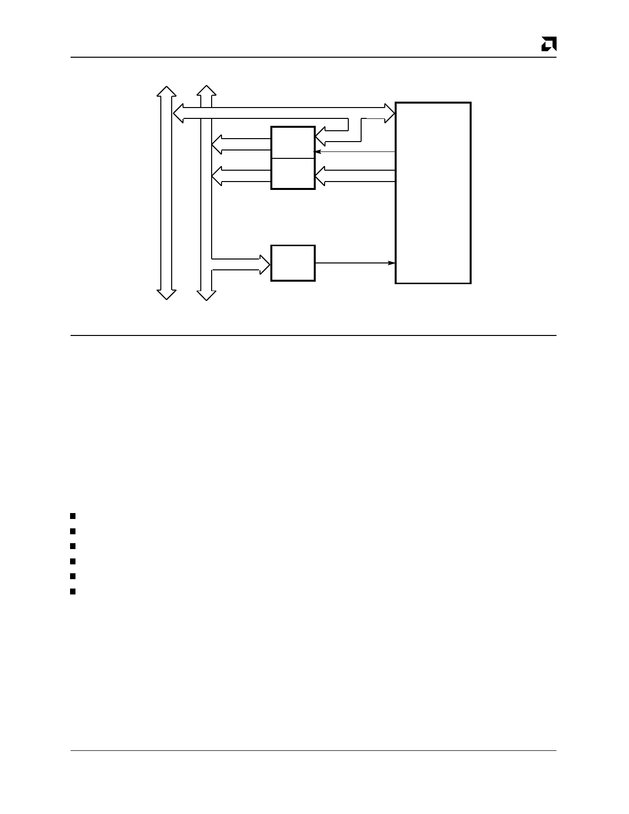
Address
Data Bus Bus
PRELIMINARY
A0–A15
A16–A23
Latch
Buffer
Data/Address
Bits 0-15
ALE
Address
Bits 16-23
C-LANCE
AMD
A0–A23
Decode
CS
Figure 2. C-LANCE/CPU Interfacing Demultiplexed Bus
17881B-6
During initialization, the CPU loads the starting address
of the initialization block into two internal control regis-
ters. The C-LANCE has four internal control and status
registers (CSR0, 1, 2, 3) which are used for various
functions, such as the loading of the initialization block
address, and programming different modes and status
conditions. The host processor communicates with the
C-LANCE during the initialization phase, for demand
transmission, and periodically to read the status bits fol-
lowing interrupts. All other transfers to and from the
memory are automatically handled as DMA.
Interrupts to the microprocessor are generated by the
C-LANCE upon:
completion of its initialization routine
the reception of a packet
the transmission of a packet
transmitter timeout error
a missed packet
memory error
The cause of the interrupt is ascertained by reading
CSR0. Bit (06) of CSR0, (INEA), enables or disables
interrupts to the microprocessor. In systems where poll-
ing is used in place of interrupts, bit (07) of CSR0,
(INTR), indicates an interrupt condition.
The basic operation of the C-LANCE consists of two dis-
tinct modes: transmit and receive. In the transmit mode,
the C-LANCE chip directly accesses data (in a transmit
buffer) in memory. It prefaces the data with a preamble,
start frame delimiter (SFD), and calculates and appends
a 32-bit CRC. On transmission, the first byte of data
loads into the 48-byte Transmit FIFO; the C-LANCE
then begins to transmit preamble while simultaneously
loading the rest of the packet into Transmit FIFO for
transmission.
In the receive mode, packets are sent via the Am7992B
SlA to the C-LANCE. The packets are loaded into the
64-byte Receive FIFO for preparation of automatic
downloading into buffer memory. A CRC is calculated
and compared with the CRC appended to the data pack-
et. If the calculated CRC does not agree with the packet
CRC, an error bit is set.
Addressing
Packets can be received using three different destina-
tion addressing schemes: physical, logical and
promiscuous.
The first type is a full comparison of the 48-bit destina-
tion address in the packet with the node address that
was programmed into the C-LANCE during an initializa-
tion cycle. There are two types of logical addresses.
One is group type mask where the 48-bit address in the
packet is put through a hash filter to map the 48-bit
physical addresses into 1 of 64 logical groups. If any of
these 64 groups have been preselected as the logical
address, then the 48-bit address is stored in main mem-
ory. At this time, a look up is performed by the host com-
puter comparing the 48-bit incoming address with the
pre-stored 48-bit logical address. This mode can be
useful if sending packets to all of a particular type of de-
vice simultaneously (i.e., send a packet to all file servers
or all printer servers). Additional details on logical ad-
dressing can be found in the INITIALIZATION section
Am79C90
9
Share Link: 