STK12C68-SF55M 查看數據表(PDF) - Simtek Corporation
零件编号
产品描述 (功能)
生产厂家
STK12C68-SF55M Datasheet PDF : 13 Pages
| |||
STK12C68
SOFTWARE NONVOLATILE RECALL
A software RECALL cycle is initiated with a sequence
of READ operations in a manner similar to the soft-
ware STORE initiation. To initiate the RECALL cycle,
the following sequence of E controlled READ opera-
tions must be performed:
1. Read address
2. Read address
3. Read address
4. Read address
5. Read address
6. Read address
0000 (hex)
1555 (hex)
0AAA (hex)
1FFF (hex)
10F0 (hex)
0F0E (hex)
Valid READ
Valid READ
Valid READ
Valid READ
Valid READ
Initiate RECALL cycle
Internally, RECALL is a two-step procedure. First, the
SRAM data is cleared, and second, the nonvolatile
information is transferred into the SRAM cells. After
the tRECALL cycle time the SRAM will once again be
ready for READ and WRITE operations. The RECALL
operation in no way alters the data in the Nonvolatile
Elements. The nonvolatile data can be recalled an
unlimited number of times.
AutoStore™ OPERATION
The STK12C68 can be powered in one of three
modes.
During normal AutoStore™ operation, the
STK12C68 will draw current from VCCX to charge a
capacitor connected to the VCAP pin. This stored
charge will be used by the chip to perform a single
STORE operation. After power up, when the voltage
on the VCAP pin drops below VSWITCH, the part will
automatically disconnect the VCAP pin from VCCX and
initiate a STORE operation.
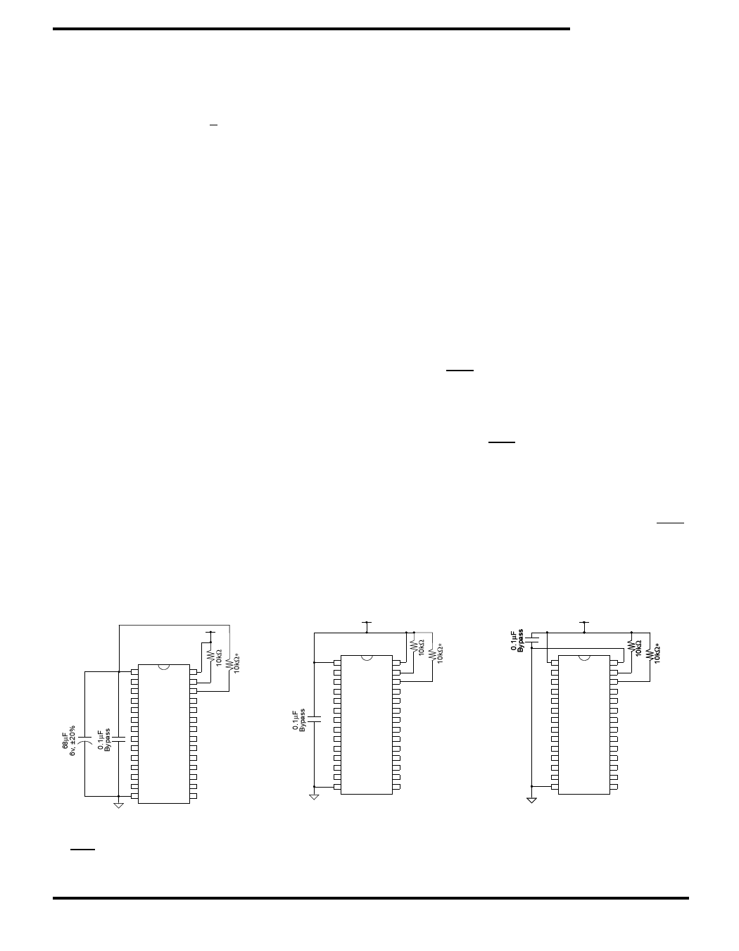
Figure 2 shows the proper connection of capacitors
for automatic store operation. A charge storage
capacitor having a capacity of between 68µF and
220µF (± 20%) rated at 6V should be provided.
In system power mode (Figure 3), both VCCX and
VCAP are connected to the + 5V power supply without
the 68µF capacitor. In this mode the AutoStore™
function of the STK12C68 will operate on the stored
system charge as power goes down. The user must,
however, guarantee that VCCX does not drop below
3.6V during the 10ms STORE cycle.
If an automatic STORE on power loss is not required,
then VCCX can be tied to ground and + 5V applied to
VCAP (Figure 4). This is the AutoStore™ Inhibit
mode, in which the AutoStore™ function is disabled.
If the STK12C68 is operated in this configuration,
references to VCCX should be changed to VCAP
throughout this data sheet. In this mode, STORE
operations may be triggered through software con-
trol or the HSB pin. It is not permissable to change
between these three options “on the fly”.
In order to prevent unneeded STORE operations,
automatic STOREs as well as those initiated by
externally driving HSB low will be ignored unless at
least one WRITE operation has taken place since the
most recent STORE or RECALL cycle. Software-
initiated STORE cycles are performed regardless of
whether a WRITE operation has taken place. An
optional pull-up resistor is shown connected to HSB.
This can be used to signal the system that the
AutoStore™ cycle is in progress.
1
28
27
26
+
1
28
27
26
1
28
27
26
14
15
Figure 2: AutoStore™ Mode
14
15
Figure 3: System Power Mode
*If HSB is not used, it should be left unconnected.
14
15
Figure 4: AutoStore™
Inhibit Mode
October 2003
9 Document Control # ML0008 rev 0.4
Share Link: 