TDA16846(2000) 查看數據表(PDF) - Infineon Technologies
零件编号
产品描述 (功能)
生产厂家
TDA16846
(Rev.:2000)
(Rev.:2000)
Infineon Technologies

TDA16846 Datasheet PDF : 28 Pages
| |||
TDA 16846
TDA 16847
2
Functional Description
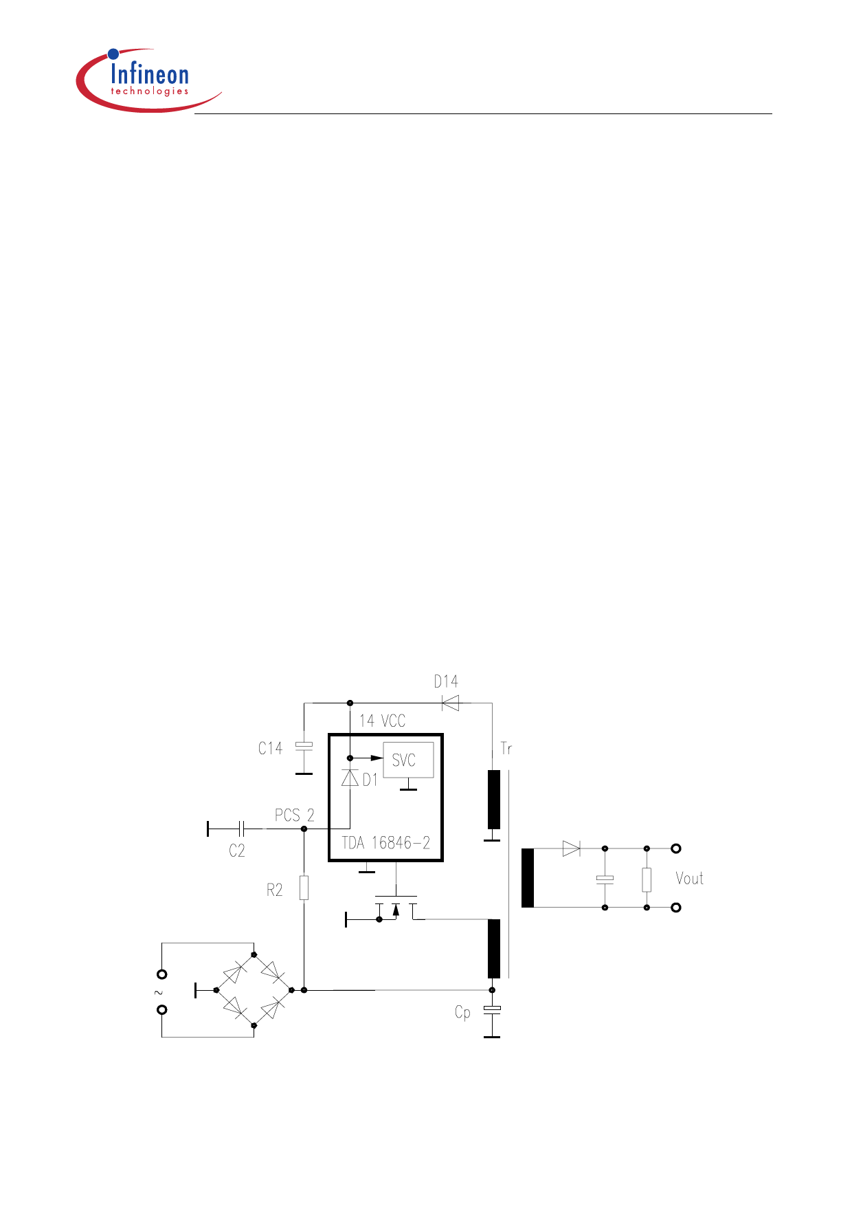
Start Up Behaviour (Pin 14)
When power is applied to the chip and the voltage V14 at Pin 14 (VCC) is less than the
upper threshold (VON) of the Supply Voltage Comparator (SVC), input current I14 will be
less than 100 µA. The chip is not active and driver output (Pin 13) and control output
(Pin 4) will be actively held low. When V14 exceeds the upper SVC threshold (VON) the
chip starts working and I14 increases. When V14 falls below the lower SVC threshold
(VOFF) the chip starts again at his initial condition. Figure 4 shows the start-up circuit and
Figure 5 shows the voltage V14 during start up. Charging of C14 is done by resistor R2 of
the “Primary Current Simulation” (see later) and the internal diode D1, so no additional
start up resistor is needed. The capacitor C14 delivers the supply current until the
auxiliary winding of the transformer supplies the chip with current through the external
diode D14.
It is recommended to switch a small RF snubber capacitor of e.g. 100 nF parallel to the
electrolytic capacitor at pin 14 as shown in the application circuits in Figures 15, 16, and
17.
D14
C14
VCC
14
SVC
TR
C2
D1
PCS 2
TDA 16846
R2
VOut
Figure 4 Startup Circuit
Cp
AES02649
Data Sheet
8
2000-01-14
Share Link: