UEI25-050-D48P-C 查看數據表(PDF) - Murata Manufacturing
零件编号
产品描述 (功能)
生产厂家
UEI25-050-D48P-C Datasheet PDF : 23 Pages
| |||
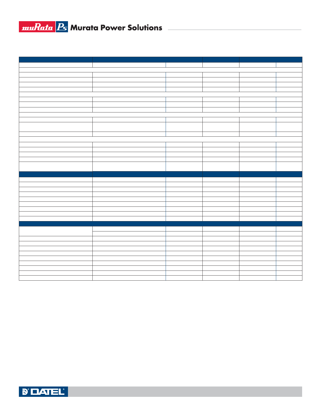
UEI25 Series
Single Output Isolated 25-Watt DC/DC Converters
FUNCTIONAL SPECIFICATIONS (CONT.) – MODEL UEI25-033-D48
OUTPUT
Total Output Power
Voltage
Nominal Output Voltage
Setting Accuracy
Output Voltage Range
Overvoltage Protection
Current
Output Current Range
Minimum Load ➂
Current Limit Inception
Short Circuit
Short Circuit Current
Short Circuit Duration (remove short for
recovery)
Short circuit protection method
Regulation ➄
Line Regulation
Load Regulation
Ripple and Noise
Temperature Coefficient
Maximum Capacitive Loading (10% ceramic,
90% Oscon)
MECHANICAL (Through Hole Models)
Outline Dimensions (no baseplate)
(Please refer to outline drawing)
Weight
Conditions ➀ ➂
See Derating
No trim
At 50% load
User-adjustable
Via magnetic feedback
98% of Vnom., after warmup
Hiccup technique, autorecovery
Output shorted to ground, no damage
Current limiting
Vin=min. to max., Vout=nom., 50% load
Iout=min. to max., Vin=48V
5 Hz- 20 MHz BW
At all outputs
Cap. ESR=<0.02Ω, full resistive load
Conditions ➀
C75 case
WxLxH
Through Hole Pin Diameter
Through Hole Pin Material
TH Pin Plating Metal and Thickness
ENVIRONMENTAL
Operating Ambient Temperature Range
Storage Temperature
Thermal Protection/Shutdown
Electromagnetic Interference
Conducted, EN55022/CISPR22
Radiated, EN55022/CISPR22
Relative humidity, non-condensing
Altitude
Nickel subplate
Gold overplate
With derating, 200 LFM
No derating, 200 LFM
Vin = Zero (no power)
Measured in center
External filter is required
To +85°C
must derate -1%/1000 feet
RoHS rating
Minimum
0.0
3.267
-1
-10
4.2
0.7575
8.5
Typical/Nominal
25.0
3.30
5
7.575
10% minimum load
10
Continuous
Maximum
25.25
3.333
+1
+10
5.7
7.575
11
0.3
Units
W
Vdc
% of Vset.
% of Vnom.
Vdc
A
% of Iout
A
A
0
Minimum
-40
-40
-55
110
10
-500
-152
50
0.02
Typical/Nominal
0.9x1.1x0.32
22.86x27.9x8.1
0.32
9.07
0.04
1.016
Copper alloy
50
5
115
B
B
RoHS-6
±0.1
±0.2
80
2000
Maximum
85
70
125
120
90
10,000
3048
% of Vout
% of Vout
mV pk-pk
% of Vnom./°C
μF
Units
Inches
mm
Ounces
Grams
Inches
mm
μ-inches
μ-inches
°C
°C
°C
°C
Class
Class
%RH
feet
meters
Notes
➀ Unless otherwise noted, all specifications are at nominal input voltage, nominal out-
put voltage and full load. General conditions are +25˚ Celsius ambient temperature,
near sea level altitude, natural convection airflow. All models are tested and specified
with external parallel 1 μF and 10 μF multi-layer ceramic output capacitors. The ex-
ternal input capacitor is 4.7 μF ceramic. All capacitors are low-ESR types wired close
to the converter. These capacitors are necessary for our test equipment and may not
be needed in the user's application.
➁ Input (back) ripple current is tested and specified over 5 Hz to 20 MHz bandwidth.
Input filtering is Cbus=220 μF, Cin=33 μF and Lbus=12 μH.
➂ All models are stable and regulate to specification under minimum (10%) load.
Operation under no load will not damage the converter but may increase regulation,
output ripple, and noise.
➃ The Remote On/Off Control is referred to -Vin.
➄ Regulation specifications describe the output voltage changes as the line voltage or
load current is varied from its nominal or midpoint value to either extreme.
www.murata-ps.com
MDC_UEI25W.B03 Page 4 of 23
Share Link: 