UPD72001C-11 查看數據表(PDF) - NEC => Renesas Technology
零件编号
产品描述 (功能)
生产厂家
UPD72001C-11 Datasheet PDF : 40 Pages
| |||
µPD72001-11, 72001-A8
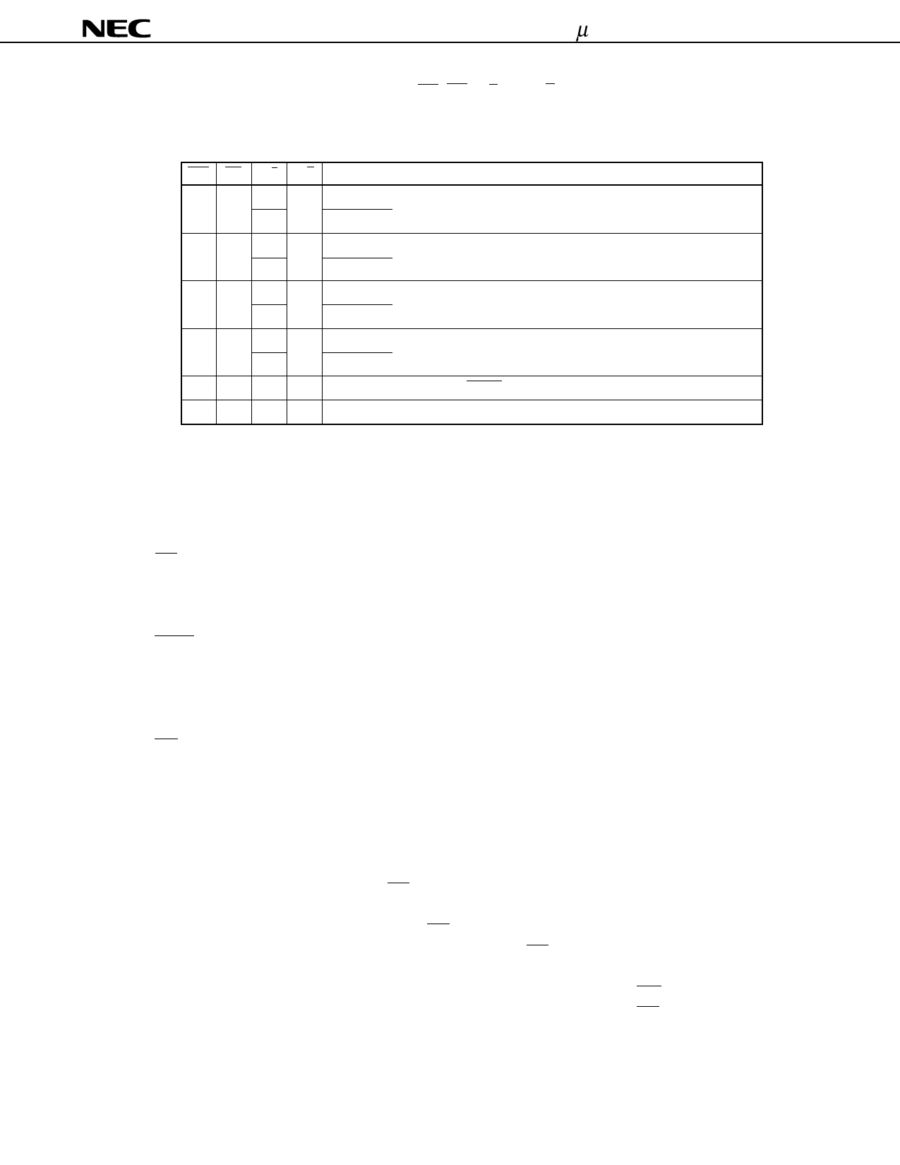
Table 1-2 shows the selection operations by WR, RD, B/A, and C/D.
Table 1-2. MPSC Control Signals and Operations
WR RD B/A C/D
Operation
L H L L Channel A
Writes transmit data to TX buffer
H
Channel B
H L L L Channel A
Reads receive data from RX buffer
H
Channel B
L H L H Channel A
Writes control register
H
Channel B
H L L H Channel A
Reads status register
H
Channel B
H H × × High-impedance state or INTAK sequence
L L × × Setting prohibited
× : Don’s Care
(9) D7 through D0 (Data Bus) ... I/O
These pins constitute a three-state 8-bit bidirectional data bus. This data bus is connected to the data bus of
the host processor to transfer control words, status, and transmit/receive data.
(10) INT (Interrupt) ... Output (open drain)
This pin outputs an interrupt request signal. If an interrupt occurs in the MPSC, it goes low (active). Because
this is an open-drain output pin, it must be pulled up.
(11) INTAK (Interrupt Acknowledge) ... Input
This pin inputs a signal to acknowledge interrupt request signals issued by the MPSC. This pin is active-low.
This pin is used when the vector mode (CR2A: D7 = “1”) is selected, and must be pulled up to “H” when the non-
vector mode (CR2A: D7 = “0”) is selected.
(12) PRI (Priority Input) ... Input
This input pin is used for an interrupt generation request signal and for an output control signal for interrupt vectors.
In the normal operation mode, this pin provides an interrupt generation control function. During the INTAK
sequence, it provides an output control function for interrupt vectors. How this pin is used differs depending on
the interrupt mode.
(a) In vector mode (CR2A: D7 = “1”)
In the normal operation mode, the PRI pin is used to control generation of interrupts. When interrupt vector
output mode of Type A-3 or Type B-2 (CR2A: D5, D4, D3 = “0, 1, 0” or “1, 0, 0”) is selected, interrupts can
be generated regardless of whether the PRI pin is “L” or “H”.
If any other interrupt vector output mode is selected, the PRI pin must be kept “L” to enable generation of
interrupts.
During the INTAK sequence, an interrupt vector is output if “L” is input to the PRI pin in any interrupt vector
output mode, and output of the interrupt vector is disabled if “H” is input to PRI.
9
Share Link: 