VSC8169QR 查看數據表(PDF) - Vitesse Semiconductor
零件编号
产品描述 (功能)
生产厂家
VSC8169QR Datasheet PDF : 18 Pages
| |||
VITESSE
SEMICONDUCTOR CORPORATION
OC-48 (FEC) 16:1 SONET/SDH
MUX with Clock Generator
Preliminary Data Sheet
VSC8169
Supplies
The VSC8169 is specified as a LVPECL device with a single positive 3.3V supply. Should the user desire
to use the device in an ECL environment with a negative 3.3V supply, then VCC will be ground and VEE will be
-3.3V. If used with VEE tied to -3.3V, the TTL control signals are still referenced to VEE.
Decoupling of the power supplies is a critical element in maintaining the proper operation of the part. It is
recommended that the VCC power supply be decoupled using a 0.1µF and 0.01µF capacitor placed in parallel
on each VCC power supply pin as close to the package as possible. If room permits, a 0.001µF capacitor should
also be placed in parallel with the 0.1µF and 0.01µF capacitors mentioned above. Recommended capacitors are
low-inductance ceramic SMT X7R devices. For the 0.1µF capacitor, a 0603 package should be used. The
0.01µF and 0.001µF capacitors can be either 0603 or 0402 packages.
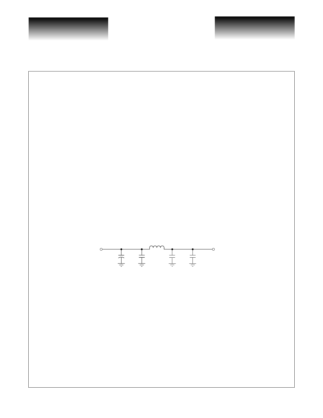
Extra care needs to be taken when decoupling the analog power supply pins (labeled VCCANA). In order to
maintain the optimal jitter and loop bandwidth characteristics of the PLL contained in the VSC8169, the analog
power supply pins should be filtered from the main power supply with a 10µH C-L-C pi filter. If preferred, a
ferrite bead may be used to provide the isolation. The 0.1µF and 0.01µF decoupling capacitors are still required
and must be connected to the supply pins between the device and the C-L-C pi filter (or ferrite bead).
For low frequency decoupling, 47µF tantalum low inductance SMT caps are sprinkled over the board’s
main +3.3V power supply and placed close to the C-L-C pi filter.
If the device is being used in an ECL environment with a -3.3V supply, then all references to decoupling
VCC must be changed to VEE, and all references to decoupling 3.3V must be changed to -3.3V.
Figure 8: PLL Power Supply Decoupling Scheme
VCC
10 F
0.1 F
VEE
10 H
0.1 F
0.01 F
VCC_ANA
VEE_ANA
Page 6
© VITESSE SEMICONDUCTOR CORPORATION • 741 Calle Plano • Camarillo, CA 93012
Tel: (800) VITESSE • FAX: (805) 987-5896 • Email: prodinfo@vitesse.com
Internet: www.vitesse.com
G52230-0, Rev 3.6
01/02/01
Share Link: 