WAN-0129 查看數據表(PDF) - Wolfson Microelectronics plc
零件编号
产品描述 (功能)
生产厂家
WAN-0129
Wolfson Microelectronics plc

WAN-0129 Datasheet PDF : 3 Pages
| |||
w
WAN-0129
Decoupling and Layout Methodology
for Wolfson DACs, ADCs and CODECs
INTRODUCTION
APPLICATION
GROUNDING
DIGITAL SUPPLY
This application note looks at the general decoupling and layout practice required for Wolfson
converters to achieve maximum performance in a typical high-speed mixed-signal circuit.
Wolfson DACs, ADCs and CODECs have both digital and analogue interfaces. It is important that
noise is minimised to get the maximum converter performance. In our datasheets there are a
number of supply pins on each chip. They are labelled according to their internal connection, not
necessarily how they should be connected externally. The datasheets show typical supply
connections and decoupling arrangements and this report goes into further details.
First consider the grounding of the IC. Ideally the circuit board will have a single continuous ground
plane, with all ground pins connected to it. The components will be located so that high-speed digital
devices are kept away from analogue devices, so that noise currents do not stray where they are not
wanted.
In some cases a cut between analogue and digital planes is required, because the component
positions cannot be optimised. In this case the analogue and digital grounds must be connected
under the converter with a wide copper track. Just using a zero-ohm link may not provide a good
enough connection in some circumstances. Ensure any tracks going from the board’s analogue
section to the digital section (e.g. data lines and clocks) are tracked over the ground connection, not
the cut, to minimise loop area for the return currents. Wolfson converters are designed with a pin-out
which ensures tracks need only go over the appropriate ground plane. If you have other high-speed
currents (including ESD currents) flowing between analogue and digital grounds, make sure this is
not the only connection between them, or you will make the converter performance worse.
Digital supply pins can be connected to the main digital supply rail if the noise levels are not too high.
If there is no nearby digital supply, or it is too noisy, then one can be made from the analogue supply
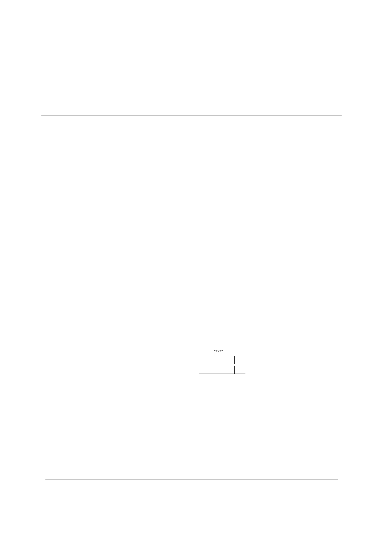
using an LC filter like below: this will make sure the noise does not go back to the analogue supply.
AVdd
10µ H
DVdd
0.1µ F
Figure 1 Converter Digital Supply from Analogue Supply
We name the digital pins like this: DVDD, DCVDD. Be sure to place a 0.1µF multi-layer ceramic
capacitor close to each of these pins (within 3mm) to decouple it properly to DGND. If there is no
large-value capacitor within 50mm, then also add one 10µF low-ESR capacitor per rail. This can be
multi-layer ceramic, low-ESR tantalum or low-ESR organic semiconductor electrolytic type. Check
the datasheet shows the part has less than 200mΩ ESR for best performance.
WOLFSON MICROELECTRONICS plc
www.wolfsonmicro.com
January 2003, Rev 1.0
Copyright 2003 Wolfson Microelectronics plc
Share Link: