NE5241 查看數據表(PDF) - Philips Electronics
零件编号
产品描述 (功能)
生产厂家
NE5241 Datasheet PDF : 6 Pages
| |||
Philips Semiconductors
Dolby ADM digital audio decoder
Product specification
NE5241
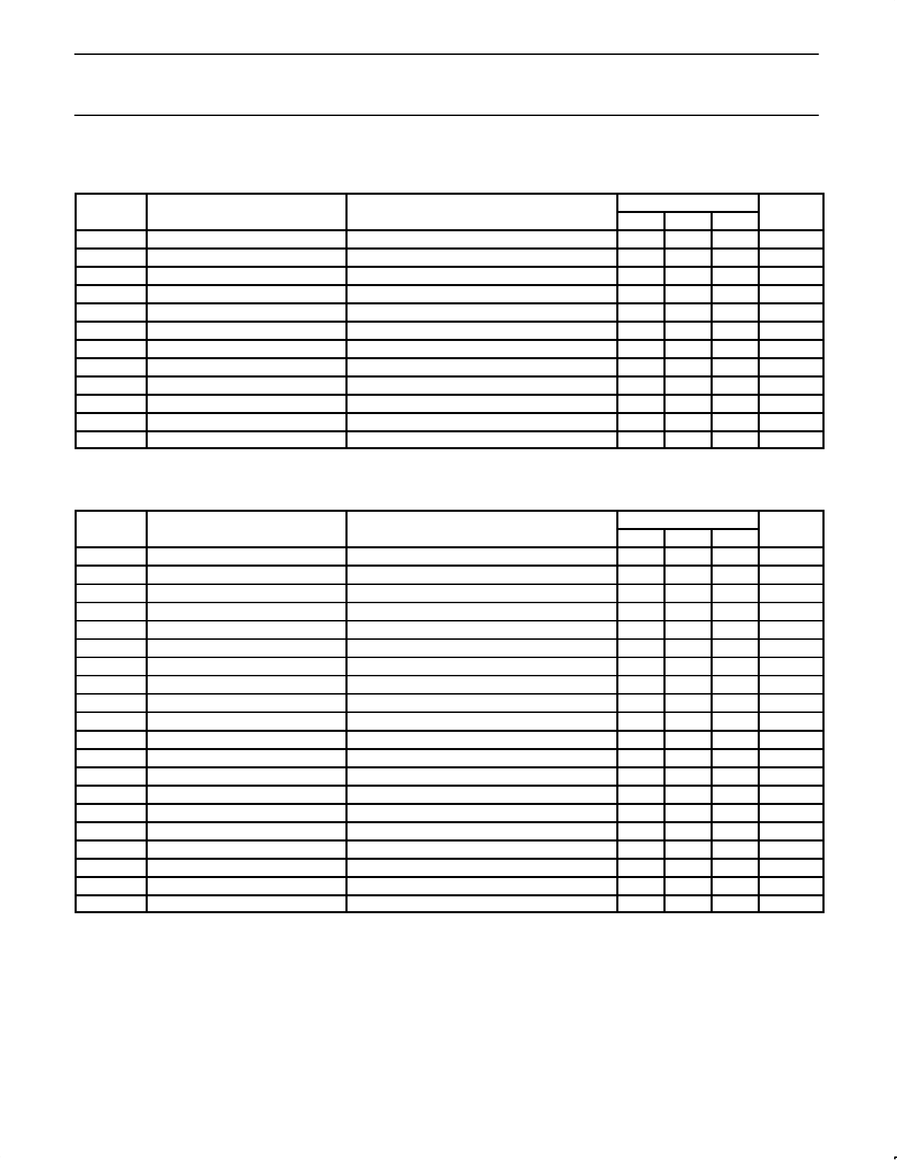
DC ELECTRICAL CHARACTERISTICS
All specifications are at TA=25°C, VDD=5V, VCC=12V. Test circuit Figure 1.
SYMBOL
PARAMETER
TEST CONDITIONS
VCC
Analog supply voltage
VDD
Digital supply voltage
ICC
Analog supply current
IDD
Digital supply current
VIH
HIGH level input voltage
VIL
LOW level input voltage
IIH
HIGH level input current
IIL
LOW level input current
tS
Data setup time
tH
Data hold time
IB
Control signal buffer bias current
Integrating amp gain
Pins SS, AD, EM
Pins SS, AD, EM = 2V
Pins SS, AD, EM = 0.8V
LIMITS
Min Typ Max
10.8 12 13.2
4.7
5
5.3
25
40
12
20
2.0
0.8
1
10
1
5
150
150
10
30
22
UNIT
V
V
mA
mA
V
V
µA
µA
ns
ns
nA
dB
AC ELECTRICAL CHARACTERISTICS
All specifications are at TA=25°C, VDD=5V, VCC=12V, Audio data rate = 204kHz. 0dB is defined as 0.775VRMS. Test circuit Figure 4.
SYMBOL
PARAMETER
Output voltage (reference level)1
TEST CONDITIONS
LIMITS
Min Typ Max
–6 –4.5 –2.5
UNIT
dBu
Channel balance (reference level)1
Channel balance change2
20% < SS < 80%
0.2
1.2
dB
0.2
1.0
dB
Channel balance change2
Step-size tracking error3
Step-size tracking error3
10% < SS < 90%
20% < SS < 80%
10% < SS < 90%
0.4
1.5
dB
0.5
3.0
dB
1.0
4.0
dB
Headroom4
Noise5
20Hz – 20kHz
13
–80 –78
dBu
Noise5
Mute noise6
CCIR/ARM
CCIR/ARM
–89 –85
dBu
–93 –88
dBu
THD
THD
Dynamic range7
Total harmonic distortion1
Total harmonic distortion8
0dB (ref level)
+13dB (max level)
98
0.8
0.2
%
0.13 0.5
%
Variable de-emph calibration error9
Freq. response error
Freq. response error
Freq. response error
Dynamic offset, emphasis10
Dynamic offset, step-size11
8kHz EM = 40%
2kHz EM = 10%
12kHz EM = 60%
15kHz EM = 70%
AC measurement
AC measurement
–1
0.2
1
dB
–1.8 0.2
1.5
dB
–2.3 0.25 2.3
dB
–2.5 0.5
2.5
dB
–43 –30
dB
–39 –24
dB
Channel separation
1kHz
75
dB
NOTES: Test patterns referred to are produced by the Dolby Cat. No. 346 ADM Test Data Generator.
1. Dolby ADM reference level, Dolby test pattern 00. This is 10dB below the nominal 100% modulation level.
2. The channel balance may change over the operating range. This specification is the channel balance change from the intial channel
balance which was measured at reference level.
3. The gain should change by 36.12dB as the step-size data is changed from 20% to 80% duty cycle, or 48.16dB as the data changes from
10% to 90%. The tracking error is the amount by which the gain change deviates from the desired value.
4. This is headroom over Dolby ADM reference level.
5. Idling data patterns, Dolby test pattern 02 with respect to test 01.
6. Muted data patterns, Dolby test pattern 04.
7. Difference between output voltage plus headroom, and CCIR/ARM weighted mute noise level.
8. Test level is 13dB over Dolby ADM reference level. Dolby test pattern 08.
9. Measured at 8.00kHz, with emphasis data at 40% duty cycle. This may be trimmed to zero by adjusting the resistor at Pin 17.
10. Dolby test pattern 48 relative to test 00. Duty cycle alternates from 10 to 70%.
11. Dolby test pattern 49 relative to test 00. Duty cycle alternates from 10 to 70%.
March 19, 1992
3
Share Link: 