74LV153 查看數據表(PDF) - Philips Electronics
零件编号
产品描述 (功能)
生产厂家
74LV153 Datasheet PDF : 14 Pages
| |||
Philips Semiconductors
Dual 4-input multiplexer
Product specification
74LV153
AC CHARACTERISTICS
GND = 0V; tr = tf = 2.5ns; CL = 50pF; RL =KΩ
SYMBOL
PARAMETER
WAVEFORM
CONDITION
tPHL/tPLH
Propagation delay
1ln to nY;
2ln to nY
Figures 1, 2
VCC(V)
1.2
2.0
2.7
3.0 to 3.6
1.2
tPHL/tPLH
Propagation delay
Sn to nY
Figures 1, 2
2.0
2.7
3.0 to 3.6
1.2
tPHL/tPLH
Propagation delay
nE to nY
Figures 1, 2
2.0
2.7
3.0 to 3.6
NOTES:
1. Unless otherwise stated, all typical values are measured at Tamb = 25°C
2. Typical values are measured at VCC = 3.3 V.
LIMITS
–40 to +85 °C
MIN TYP1 MAX
85
29
56
21
41
162
33
90
31
58
23
43
172
34
60
20
39
15
29
112
23
–40 to +125 °C
MIN MAX
66
49
39
70
51
41
46
34
27
UNIT
ns
ns
ns
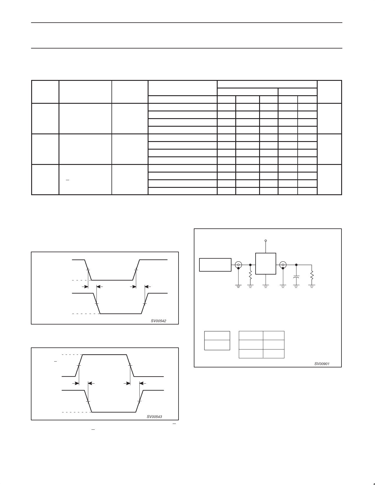
AC WAVEFORMS
VM = 1.5 V at VCC ≥ 2.7 V;
VM = 0.5 V × VCC at VCC < 2.7 V;
VOL and VOH are the typical output voltage drop that occur with the
output load.
VI
1I n, 2I n
INPUT
VM
GND
t PHL
V OH
t PLH
nY OUTPUT
VM
V OL
SV00542
Figure 1. Input (1ln, 2ln) to output (1Y, 2Y)
propagation delays.
VI
Sn, nE
INPUT
VM
GND
V OH
t PHL
t PLH
nY OUTPUT
VM
V OL
SV00543
Figure 2. Select input (S0, S1) and the output enable input (E)
to output (nYn) propagation delays.
TEST CIRCUIT
VCC
PULSE
GENERATOR
VI
RT
D.U.T.
VO
50pF
CL
RL = 1k
Test Circuit for switching times
DEFINITIONS
RL = Load resistor
CL = Load capacitance includes jig and probe capacitance
RT = Termination resistance should be equal to ZOUT of pulse generators.
TEST
tPLH/tPHL
VCC
< 2.7V
2.7–3.6V
VI
VCC
2.7V
SV00901
Figure 3. Load circuitry for switching times.
1998 Apr 28
7
Share Link: 