LTC1143 查看數據表(PDF) - Linear Technology
零件编号
产品描述 (功能)
生产厂家
LTC1143 Datasheet PDF : 20 Pages
| |||
LTC1143/LTC1143L
LTC1143L-ADJ
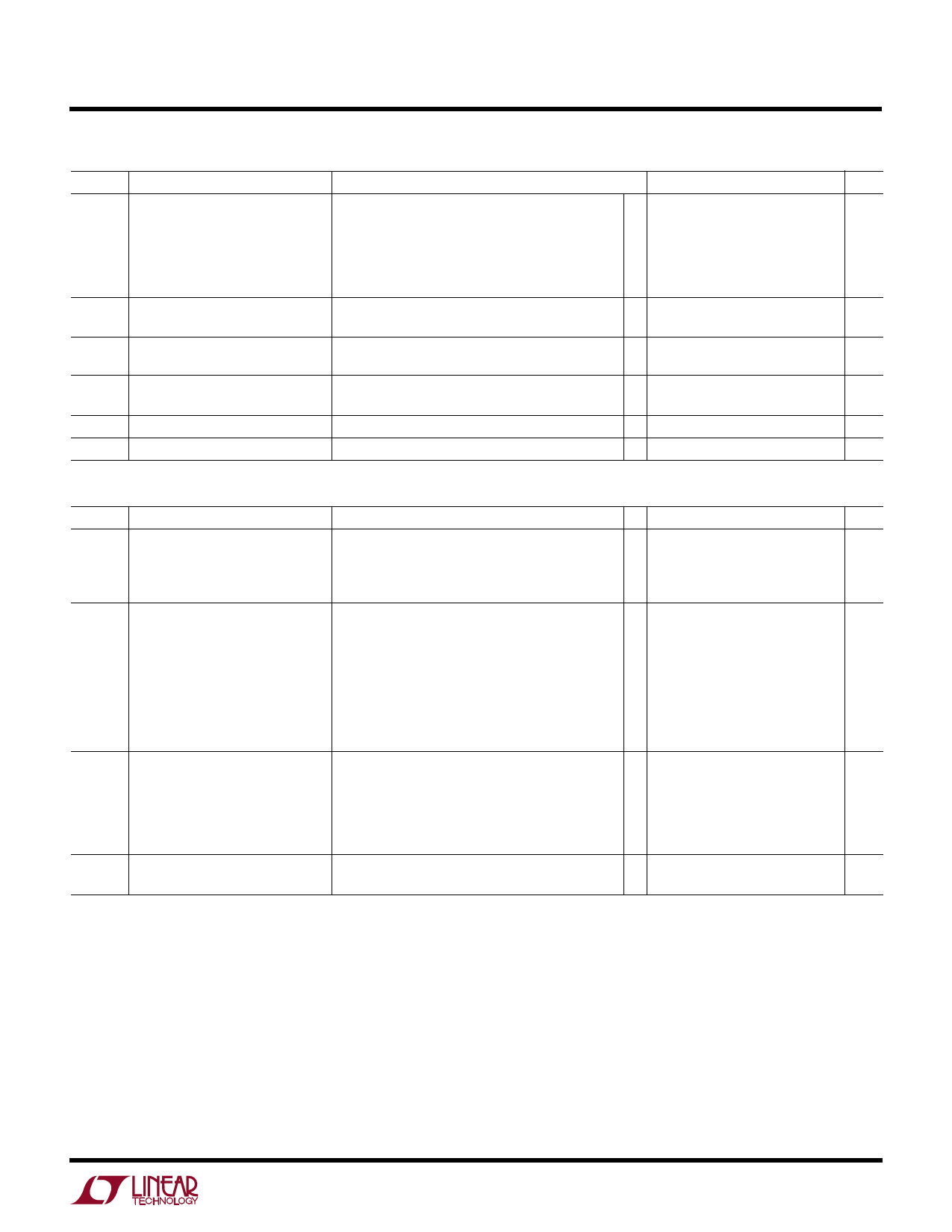
ELECTRICAL CHARACTERISTICS TA = 25°C, VIN = 10V unless otherwise noted.
SYMBOL PARAMETER
V1 to V16, Current Sense Threshold Voltage
V8 to V9
LTC1143/LTC1143L
LTC1143L-ADJ
V2, V10
I2, I10
I6, I14
Shutdown Pin Threshold
LTC1143/LTC1143L
Shutdown Pin Input Current
LTC1143/LTC1143L
CT Pin Discharge Current
tOFF
Off-Time (Note 3)
tr, tf
Driver Output Transition Times
CONDITIONS
V2 = V10 = 0V
VSENSE– = VOUT + 100mV (Forced)
VSENSE– = VOUT – 100mV (Forced)
VVSSEENNSSEE––
=
=
5V,
5V,
VFB
VFB
=
=
VOUT/4
VOUT/4
+
–
25mV
25mV
(Forced)
(Forced)
0V < VSHUTDOWN = < 8V, VIN3, VIN5 = 16V
VOUT in Regulation, VSENSE- = VOUT
VOUT = 0V
CT = 390pF, ILOAD = 700mA
CL = 3000pF (Pins 4, 12), VIN = 6V
MIN TYP MAX
UNITS
25
mV
q 130 150 170
mV
25
mV
q 130 150 170
mV
0.5
0.8
2
V
1.2
5
µA
50
70
90
µA
2
10
µA
4
5
6
µs
100 200
ns
–40°C ≤ TA ≤ 85°C (Note 4), VIN = 10V unless otherwise noted.
V2, V10
VOUT
I5, I13
V1 to V16,
V8 to V9
Feedback Voltage (LTC1143L-ADJ)
Regulated Output Voltage
LTC1143/LTC1143L
3.3V Output
5V Output
Input DC Supply Current (Note 2)
LTC1143:
Normal Mode
Sleep Mode
Shutdown
LTC1143L: Normal Mode
Sleep Mode
Shutdown
LTC1143L-ADJ: Normal Mode
Sleep Mode
Current Sense Threshold Voltage
LTC1143/LTC1143L
LTC1143L-ADJ
V2, V10
Shutdown Pin Threshold
LTC1143/LTC1143L
VIN = 9V
VIN3, VIN5 = 9V
ILOAD = 700mA
ILOAD = 700mA
V2 = V10 = 0V, 4V < VIN < 12V
V2 = V10 = 0V, 4V < VIN3 < 12V, 6V < VIN5 < 12V
V2 = V10 = 2.1V, 4V < VIN < 12V
V2 = V10 = 0V, 3.5V < VIN < 12V
V2 = V10 = 0V, 3.5V < VIN3 < 12V, 6V < VIN5 < 12V
V2 = V10 = 2.1V, 3.5V < VIN < 12V
3.5V < VIN < 12V
3.5V < VIN < 12V, VOUT ≤ 3.3V
V2 = V10 = 0V
VSENSE– = VOUT + 100mV (Forced)
VSENSE– = VOUT – 100mV (Forced)
VSENSE– = 5V, VFB = VOUT/4 + 25mV (Forced)
VSENSE– = 5V, VFB = VOUT/4 – 25mV (Forced)
1.20 1.25 1.30
V
3.17 3.33 3.43
V
4.85 5.05 5.20
V
1.6
2.4
mA
160
260
µA
10
22
µA
1.6
2.4
mA
160
260
µA
10
22
µA
1.6
2.4
mA
160
260
µA
25
mV
125 150 185
mV
25
mV
125 150 185
mV
0.55 0.8
2
V
The q denotes specifications which apply over the specified temperature
range.
Note 1: TJ is calculated from the ambient temperature TA and power
dissipation PD according to the following formula:
LTC1143 series: TJ = TA + (PD • 125°C/W)
Note 2: This supply current is for one regulator block. Total supply
current is the sum of Pin 5 and Pin 13 currents. Dynamic supply current
is higher due to the gate charge being delivered at the switching
frequency. See Applications Information.
Note 3: In applications where RSENSE is placed at ground potential, the
off-time increases approximately 40%.
Note 4: The LTC1143 series is guaranteed to meet specified performance
from 0°C to 70°C and is designed, characterized and expected to meet
these extended temperature limits, but is not tested at –40°C to 85°C.
3
Share Link: 