LTC1143 查看數據表(PDF) - Linear Technology
零件编号
产品描述 (功能)
生产厂家
LTC1143 Datasheet PDF : 20 Pages
| |||
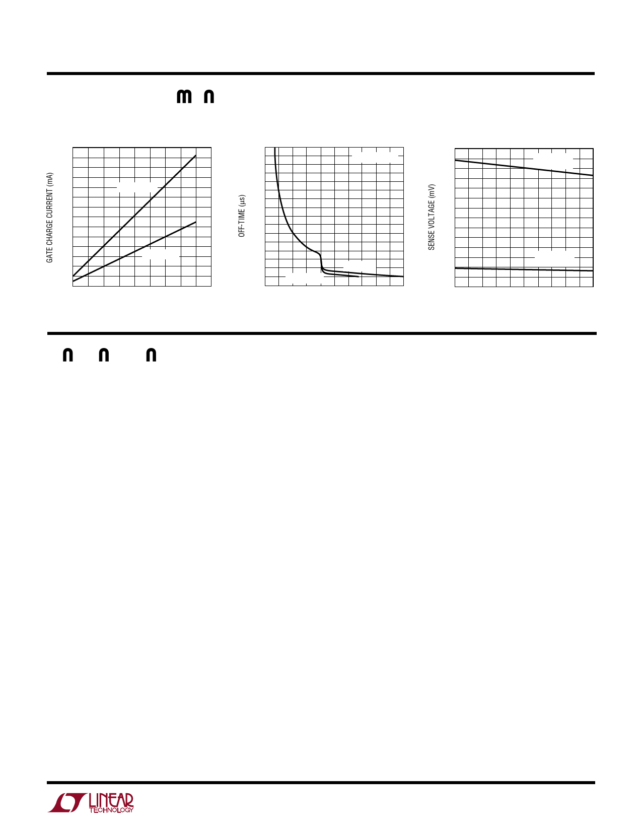
TYPICAL PERFORMANCE CHARACTERISTICS
Gate Charge Supply Current
14
12
10
QP = 100nC
8
6
4
QP = 29nC
2
0
20
80
140
200
260
OPERATING FREQUENCY (kHz)
LTC1143 G10
Off-Time vs VOUT
80
70
VSENSE = VOUT
60
50
40
30
20
10
0
0
VOUT = 3.3V
VOUT = 5V
1
2
3
4
5
OUTPUT VOLTAGE (V)
LTC1143 G11
LTC1143/LTC1143L
LTC1143L-ADJ
Current Sense Threshold Voltage
175
MAXIMUM
150
THRESHOLD
125
100
75
50
MINIMUM
25
THRESHOLD
0
0
20
40
60
80 100
TEMPERATURE (°C)
LTC1143 G12
PIN FUNCTIONS
LTC1143/LTC1143L
SENSE+3 (Pin 1): The (+) Input to the 3.3V Section Current
Comparator. A built-in offset between Pins 1 and 16 in
conjunction with RSENSE 3 sets the current trip threshold
for the 3.3V section.
SHUTDOWN 3 (Pin 2): When grounded, the 3.3V section
operates normally. Pulling Pin 2 high holds the MOSFET
off and puts the 3.3V section in micropower shutdown
mode. Requires CMOS logic level signal with tr, tf < 1µs.
Do not “float” Pin 2.
GND3 (Pin 3): 3.3V Section Ground. Two independent
ground lines must be routed separately from other grounds
to: 1) the (–) terminal of the 3.3V section output capacitor
and 2) the cathode of the Schottky diode D1 and (–)
terminal of CIN3 (see Figure 9).
P-DRIVE 3 (Pin 4): High Current Drive for Top P-Channel
MOSFET, 3.3V Section. Voltage swing at this pin is from
VIN3 to ground.
VIN5 (Pin 5): Supply Pin, 5V Section. Must be closely
decoupled to 5V power ground Pin 11.
CT5 (Pin 6): External capacitor CT5 from Pin 6 to ground sets
the operating frequency for the 5V section. (The actual
frequency is also dependent upon the input voltage.)
ITH5 (Pin 7): Gain Amplifier Decoupling Point, 5V Section.
The 5V section current comparator threshold increases
with the Pin 7 voltage.
SENSE– 5 (Pin 8): Connects to internal resistive divider
which sets the output voltage for the 5V section. Pin 8 is
also the (–) input for the current comparator on the 5V
section.
SENSE+ 5 (Pin 9): The (+) Input to the 5V Section Current
Comparator. A built-in offset between Pins 9 and 8 in
conjunction with RSENSE 5 sets the current trip threshold
for the 5V section.
SHUTDOWN 5 (Pin 10): When grounded, the 5V section
operates normally. Pulling Pin 10 high holds the 5V section
MOSFET off and puts the 5V section in micropower shut-
down mode. Requires CMOS logic level signal with tr, tf < 1µs.
Do not “float” Pin 10.
GND5 (Pin 11): 5V Section Ground. Two independent
ground lines must be routed separately from other grounds
to: 1) the (–) terminal of the 5V section output capacitor
and 2) the cathode of the Schottky diode D2 and (–)
terminal of CIN5 (see Figure 9).
P-DRIVE 5 (Pin 12): High Current Drive for Top P-Channel
MOSFET, 5V Section. Voltage swing at this pin is from
VIN5 to ground.
5
Share Link: 