MKP1848630084Y 查看數據表(PDF) - Vishay Semiconductors
零件编号
产品描述 (功能)
生产厂家
MKP1848630084Y Datasheet PDF : 20 Pages
| |||
www.vishay.com
MKP1848 DC-Link
Vishay Roederstein
PACKAGING INFORMATION
UNDC
AT 85 °C
(V)
HEIGHT
(mm)
CAP. (5)
(μF)
Ø dt
ORDERING CODE (1)
38.5
44
44
45
45
45
1200
45
50
50
50
45
65
65
UOPDC AT 70 °C = 1500 V, UOPDC AT 105 °C = 850 V
8
1.0
MKP1848580924P*
9
1.0
MKP1848590924P*
10
1.0
MKP1848610924P*
12
1.0
MKP1848612924P*
10
1.2
MKP1848610924Y*
12
1.2
MKP1848612924Y*
15
1.2
MKP1848615924Y*
20
1.2
MKP1848620924Y*
22
1.2
MKP1848622924Y*
25
1.2
MKP1848625924Y*
30
1.2
MKP1848630924Y5
60
1.2
MKP1848660924Y5 (3)
120
1.2
MKP1848712924Y5 (4)
Notes
(1) Change the * symbol with special code for the terminals
(2) SPQ = Standard Packing Quantity
(3) 6 pins
(4) 12 pins
(5) Intermediate capacitance values available on request
MASS
(g)
35
48
45
60
79
74
67
115
109
100
119
264
612
SPQ (2)
(pcs)
91
77
77
63
55
55
55
40
40
40
30
20
10
CONSTRUCTION DESCRIPTION
Low inductive wound cell elements of metallized polypropylene film, potted with resin in a flame retardant case.
SPECIFIC METHOD OF MOUNTING TO WITHSTAND VIBRATION AND SHOCK
The capacitor unit is designed for mounting on a printed circuit board.
In order to withstand vibration and shock tests, it must be insured that the stand-off pips are in good contact with the printed
circuit board.
The capacitors shall be mechanically fixed by the leads and the body clamped.
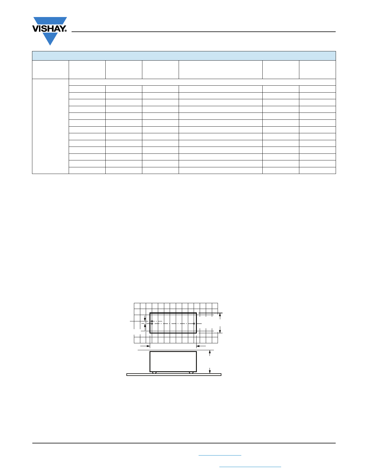
SPACE REQUIREMENTS ON PRINTED-CIRCUIT BOARD
The maximum length and width of film capacitors is shown in the figure.
For product height with seating plane as given by “IEC 60717” as reference.
For 2 pins:
Eccentricity
wmax. = w + Δw
Imax. = I + ΔI
hmax. = h + Δh
Seating plane
For the maximum product dimensions and maximum space requirements for length (lmax.), width (wmax.), and height (hmax.)
following tolerances must be taken in account in the envelopment of the components as shown in the drawings below:
• For products with 15 mm < pitch 27.5 mm, w = l = 0.5 mm, and h = 0.1 mm
• For products with pitch = 37.5 mm, w = l = 0.7 mm, and h = 0.5 mm
• For products with pitch = 52.5 mm, w = l = 1.0 mm, and h = 0.5 mm
Eccentricity defined as in drawing. The maximum eccentricity is smaller than or equal to the lead diameter of the product
concerned.
The maximum length and width of film capacitors is shown in the figure.
Revision: 25-Oct-17
11
Document Number: 28164
For technical questions, contact: dc-film@vishay.com
THIS DOCUMENT IS SUBJECT TO CHANGE WITHOUT NOTICE. THE PRODUCTS DESCRIBED HEREIN AND THIS DOCUMENT
ARE SUBJECT TO SPECIFIC DISCLAIMERS, SET FORTH AT www.vishay.com/doc?91000
Share Link: 