STR-W6753 查看數據表(PDF) - Sanken Electric co.,ltd.
零件编号
产品描述 (功能)
生产厂家
STR-W6753 Datasheet PDF : 8 Pages
| |||
STR-W6753
Quasi-Resonant Topology
Primary Switching Regulators
Features and Benefits
▪ Quasi-resonant topology IC Low EMI noise and soft
switching
▪ Bottom-skip mode Improved system efficiency over
the entire output load by avoiding increase of switching
frequency
▪ Auto-Standby mode Lowers input power at very light
output load condition
▪ Avalanche-guaranteed MOSFET Improves system-level
reliability and does not require VDSS derating
▪ 650 V / 1.70 Ω
▪ Various protections Improved system-level reliability
Continued on the next page…
Package: 6-pin TO-220
Not to scale
Description
The STR-W6753 is a quasi-resonant topology IC designed for
SMPS applications. It shows lower EMI noise characteristics
than conventional PWM solutions, especially at greater than
2 MHz. It also provides a soft-switching mode to turn on the
internal MOSFET at close to zero voltage (VDS bottom point)
by use of the resonant characteristic of primary inductance
and a resonant capacitor.
The package is a fully molded TO-220, which contains the
controller chip (MIC) and MOSFET, enabling output power up
to 58 W with universal input or 120 W with a 230 VAC input.
The bottom-skip mode skips the first bottom of VDS and turns
on the MOSFET at the second bottom point, to minimize an
increase of operating frequency at light output load, improving
system-level efficiency over the entire load range.
There are two standby modes available to reduce the input power
under very light load conditions. The first is Auto-Standby
mode, which is internally triggered by periodic sensing, and
the other is a manual standby mode, which is executed by
clamping the secondary output. In general applications, the
manual standby mode reduces the input power further compared
to Auto-Standby mode.
The soft-start mode minimizes surge voltage and reduces
power stress to the MOSFET and to the secondary rectifying
Continued on the next page…
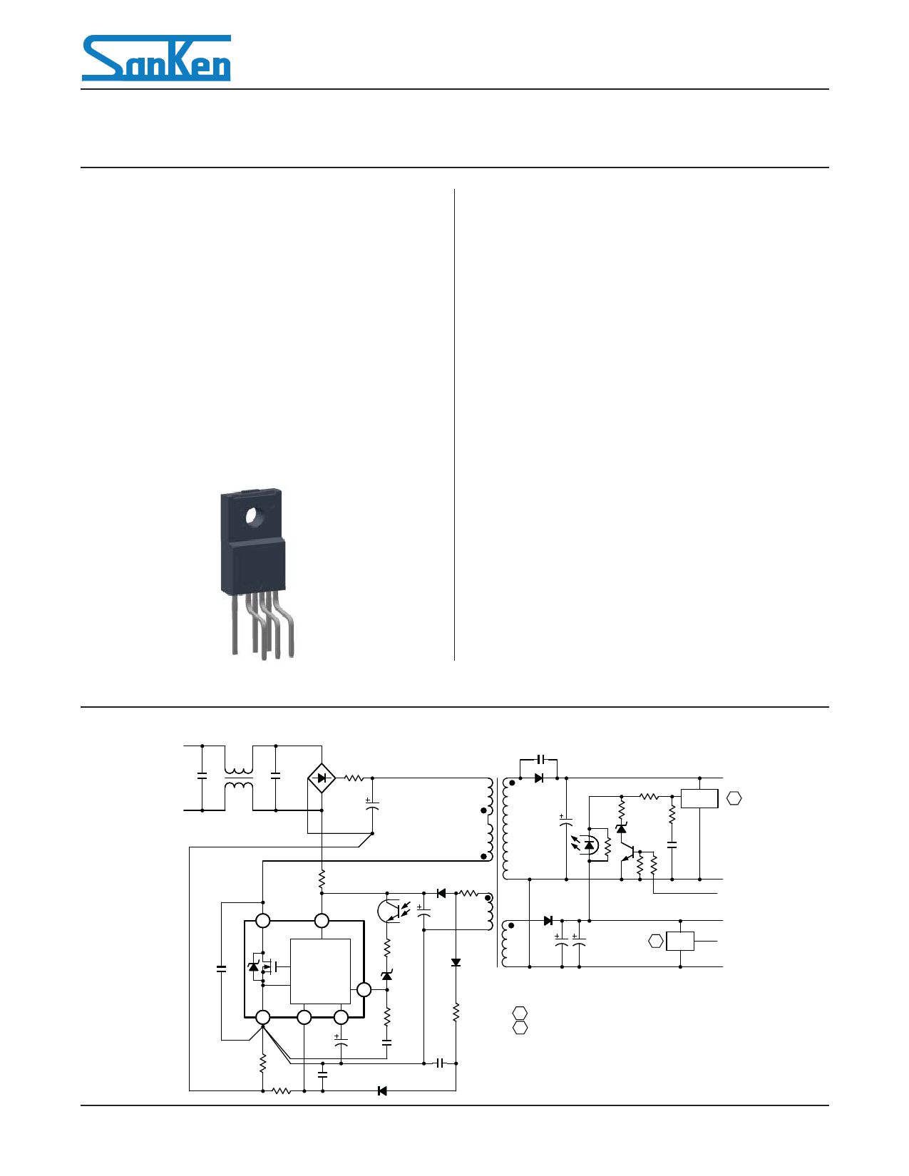
Typical Application Diagram
P
S1
+B
ErrAmp A
D
1
VCC
4
STR-W6753
Controller
(MIC)
6
FB
3
7
S/GND OCP/BD
5
RX
SS /OLP
CX
ROCP
D
S2
B SI
GND
Standby
ON/OFF
LowB
Standby
Out
GND
A For ErrAmp, Sanken SE series device recommended
B For SI, Sanken linear regulator IC recommended
28103.31
SANKEN ELECTRIC CO., LTD.
http://www.sanken-ele.co.jp/en/
Share Link: 