AD10242TZ 查看數據表(PDF) - Analog Devices
零件编号
产品描述 (功能)
生产厂家
AD10242TZ
Analog Devices

AD10242TZ Datasheet PDF : 16 Pages
| |||
AD10242
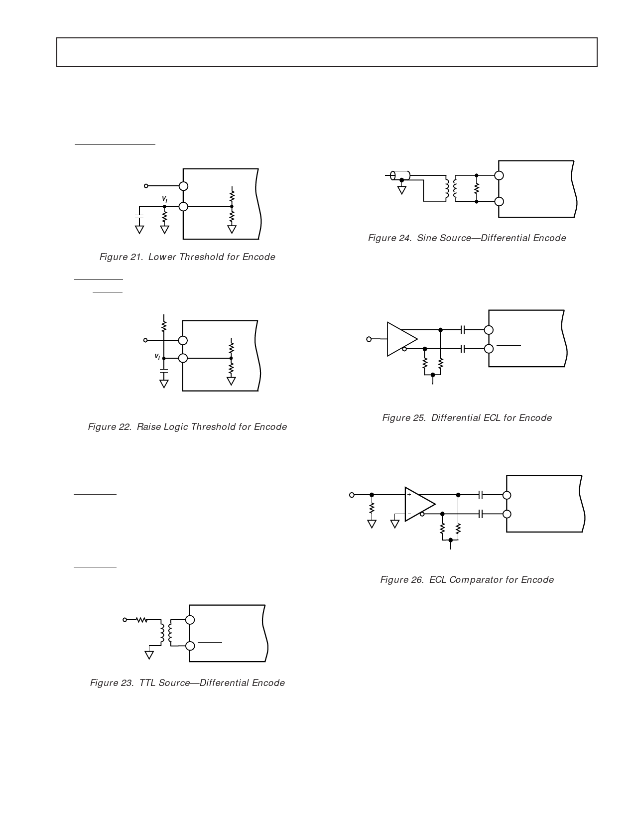
If a logic threshold other than the nominal 1.6 V is required,
the following equations show how to use an external resistor,
RX, to raise or lower the trip point (see Figure 4, R1 = 17 kΩ,
R2 = 8 kΩ).
V1
=
5R2RX
R1R2 + R1RX +
R2RX
to lower logic threshold.
ENCODE
SOURCE
Vl
0.01µF
RX
ENCODE
ENCODE
+5V
R1
R2
AD10242
Figure 21. Lower Threshold for Encode
V1
=
R2
5R2
+
R1RX
R1+ RX
to raise logic threshold.
AVCC
RX
ENCODE
SOURCE
Vl
0.01µF
ENCODE
ENCODE
+5V
R1
R2
AD10242
If no TTL source is available, a clean sine wave may be substi-
tuted. In the case of the sine source, the matching network is
shown below. Since the matching transformer specified is a 1:1
impedance ratio, R, the load resistor should be selected to
match the source impedance. The input impedance of the
AD9042 is negligible in most cases.
SINE
SOURCE
T1-1T
ENCODE
R
AD10242
ENCODE
Figure 24. Sine Source—Differential Encode
If a low jitter ECL clock is available, another option is to ac-
couple a differential ECL signal to the encode input pins as
shown below. The capacitors shown here should be chip capaci-
tors but do not need to be of the low inductance variety.
ECL
GATE
510Ω
0.1µF
0.1µF
510Ω
–VS
ENCODE
AD10242
ENCODE
Figure 22. Raise Logic Threshold for Encode
While the single ended encode will work well for many applica-
tions, driving the encode differentially will provide increased
performance. Depending on circuit layout and system noise, a
1 dB to 3 dB improvement in SNR can be realized. It is recom-
mended that the encode signal be ac-coupled into the ENCODE
and ENCODE pins.
The simplest option is shown below. The low jitter TTL signal
is coupled with a limiting resistor, typically 100 Ω, to the pri-
mary side of an RF transformer (these transformers are inexpen-
sive and readily available; Part No. in figure is from Mini-
Circuits). The secondary side is connected to the ENCODE
and ENCODE pins of the converter. Since both encode inputs
are self-biased, no additional components are required.
100Ω T1-1T
TTL
ENCODE
AD10242
ENCODE
Figure 25. Differential ECL for Encode
As a final alternative, the ECL gate may be replaced by an ECL
comparator. The input to the comparator could then be a logic
signal or a sine signal.
AD96687 (1/2)
50Ω
510Ω
0.1µF
0.1µF
510Ω
ENCODE
AD10242
ENCODE
–VS
Figure 26. ECL Comparator for Encode
Care should be taken not to overdrive the encode input pin
when ac coupled. Although the input circuitry is electrically pro-
tected from over or under voltage conditions, improper circuit
operations may result from overdriving the encode input pin.
Figure 23. TTL Source—Differential Encode
REV. A
–11–
Share Link: