MC145200EVK 查看數據表(PDF) - Motorola => Freescale
零件编号
产品描述 (功能)
生产厂家
MC145200EVK Datasheet PDF : 17 Pages
| |||
Power for the 5 V logic is provided by U4 (78M05). U4 steps down the 8.5 V from U3. Output voltage from
U4 passes through J4, the 5 V cut–trace and jumper. To supply separate power to logic, the trace under
J4 is cut, J4 shorting plug is removed, and 5 V is applied to J7. U3 and U4 are cascaded to lower their
individual voltage drops. This lowers the power dissipated in the regulators.
The PLL loop is composed of the PLL device (U1), 733 – 751 MHz VCO (M1), passive loop filter (R11,
R12, C4, C5, C6) and second harmonic filter amplifier (U6). A passive loop filter was used to keep the
design simple, reduce noise, and reduce the quantity of traces susceptible to stray pickup. About 56 dB
rejection of fundamental and 23 dB gain is provided by the harmonic filter amplifier. This allows the ’200
or ’201 to lock at 1466 – 1502 MHz. The harmonic filter amplifier is bypassed on the ’190 and ’191.
A single VCO model is used for all boards. It is an internal Motorola part which is not sold for other ap-
plications. The ’190 and ’191 have different frequency ranges. This is due to the lower charge pump sup-
ply voltage of the ’191. A common 10 MHz tune range allows the same loop filter components to be used.
For the same reason, the ’200 and ’201 tune range is 20 MHz with double the step size of the ’190 or
’191. RF is fed to the PLL chip Fin input through a voltage divider. These two resistors terminate the PLL
chip RF input with 50 ohms and provide isolation.
All boards use a phase detector current of 2 mA. J1 and J2 are removable jumpers and cut traces. They
are used as connection points for a current measurement of VPD or VCC. J11 and J12 are wire jumpers
that select 5 V or 8.5 V for VPD. A potentiometer VR1 is used to set M2 (14.4 MHz TCXO) on frequency.
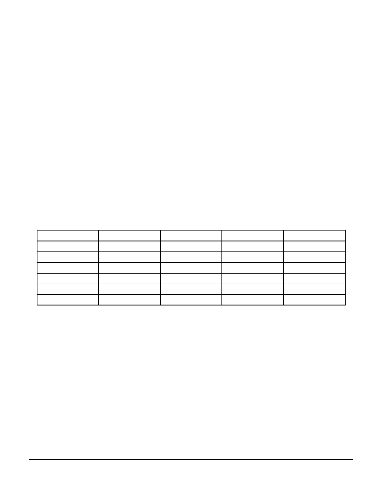
COMPONENTS UNIQUE TO EACH EVK
ÁÁÁÁÁÁÁÁÁCÁÁÁÁÁÁÁÁÁomÁÁÁÁÁÁÁÁÁpoÁÁÁÁÁÁÁÁÁnCJJeURR11ÁÁn2ÁÁÁÁÁÁÁ12812t2sÁÁÁÁÁÁÁÁÁthaÁÁÁÁÁÁÁÁÁt arÁÁÁÁÁÁÁÁÁe nÁÁÁÁÁÁÁÁot MtÁÁÁÁÁÁÁÁc’hnn1oCeoo49nÁÁÁÁÁÁÁÁ1tt070sn4uuaeΩkE5ssmcÁÁÁÁÁÁÁÁΩV1eetee9ddKdÁÁ0ÁÁÁÁÁÁonÁÁÁÁÁÁÁÁÁallÁÁÁÁÁÁÁÁÁEVÁÁKÁÁÁÁÁÁÁMsc’nn1oÁÁÁÁÁÁÁÁÁaCoo29nr1tt02e1n4ÁÁÁÁÁÁÁÁÁuueΩkgE5sscΩiV1eevtÁÁÁÁÁÁÁÁÁe9eddKd1nÁÁÁÁÁÁÁÁÁin tÁÁÁÁÁÁÁÁÁheÁÁÁÁÁÁÁÁÁfollÁÁMÁÁÁÁÁÁÁoc’nn2owC1oo40niÁÁÁÁÁÁÁÁÁ1n.tt70n04guuekE5pssÁÁÁÁÁÁÁÁÁctΩV2aeeFte0bddKdÁÁÁÁÁÁÁÁÁ0le:ÁÁÁÁÁÁÁÁÁÁÁÁÁÁÁÁÁÁÁÁÁÁÁÁÁÁÁMc’nn2oÁÁÁÁÁÁÁÁÁC1oo20n1.tt21n0ÁÁ4ÁÁÁÁÁÁÁuuekE5psscΩV2eeFtÁÁÁÁÁÁÁÁÁe0ddKd1ÁÁÁÁÁÁÁÁÁÁÁÁÁÁÁÁÁÁ
EXTERNAL REFERENCE INPUT
As shipped, all boards are configured for a 14.4 MHz TCXO (supplied). To use an external reference,
disconnect J13 and connect J9. Use a reference signal at J10 which complies with data sheet require-
ments. Then modify the reference frequency in the program main menu to reflect the changes made ( [F]
menu item ).
DATA TRANSFER FROM COMPUTER TO EVK
To control the serial input EVK with the parallel printer port, a conversion is done. Printer cards are de-
signed to output 8 bits through eight lines. A bit mask is used to obtain the bit combination for the three
required output lines (Data, Clock, Load). As bytes are sent to the printer card in sequence, it appears to
be a serial transfer. The printer port was used because data transfer using the serial port would have
been much slower. A standard IBM PC can support a parallel port data rate of 4.77 MHz.
MC145190EVK
6
MOTOROLA
Share Link: 