BAV20W 查看數據表(PDF) - Linear Technology
零件编号
产品描述 (功能)
生产厂家
BAV20W Datasheet PDF : 24 Pages
| |||
LT8300
Applications Information
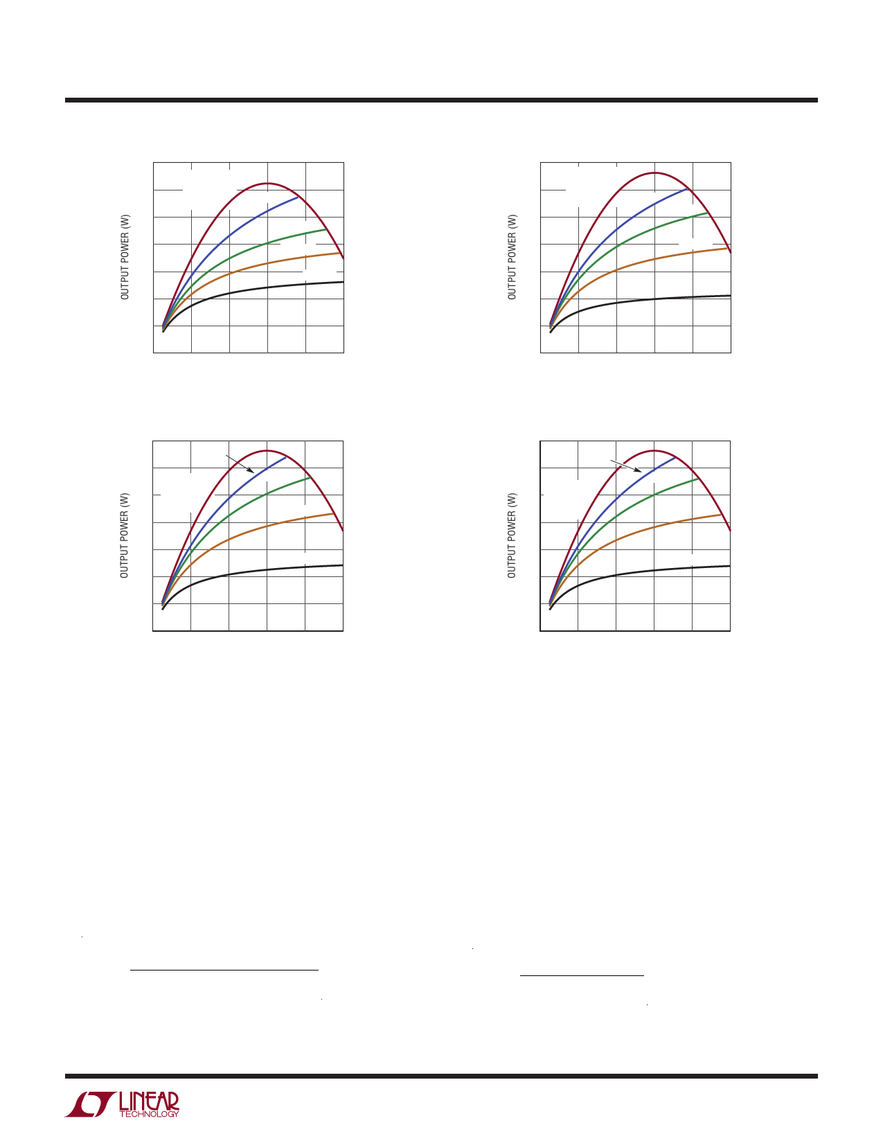
3.5
MAXIMUM
3.0
OUTPUT
POWER
N = 12:1
2.5
N = 8:1
2.0
N = 6:1
1.5
N = 4:1
1.0
0.5
0
0
20
40
60
80 100
INPUT VOLTAGE (V)
8300 F01
Figure 1. Output Power for 3.3V Output
3.5
N = 4:1
3.0
MAXIMUM
2.5 OUTPUT
POWER
2.0
N = 3:1
N = 2:1
1.5
N = 1:1
1.0
0.5
0
0
20
40
60
80 100
INPUT VOLTAGE (V)
8300 F03
Figure 3. Output Power for 12V Output
3.5
MAXIMUM
3.0
OUTPUT
POWER N = 8:1
N = 6:1
2.5
2.0
N = 4:1
1.5
N = 2:1
1.0
0.5
0
0
20
40
60
80 100
INPUT VOLTAGE (V)
8300 F02
Figure 2. Output Power for 5V Output
3.5
N = 2:1
3.0
2.5
MAXIMUM
OUTPUT
POWER
2.0
N = 3:2
N = 1:1
1.5
N = 1:2
1.0
0.5
0
0
20
40
60
80 100
INPUT VOLTAGE (V)
8300 F04
Figure 4. Output Power for 24V Output
Primary Inductance Requirement
The LT8300 obtains output voltage information from the
reflected output voltage on the SW pin. The conduction
of secondary current reflects the output voltage on the
primary SW pin. The sample-and-hold error amplifier needs
a minimum 350ns to settle and sample the reflected output
voltage. In order to ensure proper sampling, the second-
ary winding needs to conduct current for a minimum of
350ns. The following equation gives the minimum value
for primary-side magnetizing inductance:
( ) LPRI
≥
tOFF(MIN)
• NPS • VOUT
ISW(MIN)
+
VF
tOFF(MIN) = Minimum switch-off time = 350ns
ISW(MIN) = Minimum switch current limit = 52mA
In addition to the primary inductance requirement for
the minimum switch-off time, the LT8300 has minimum
switch-on time that prevents the chip from turning on
the power switch shorter than approximately 160ns. This
minimum switch-on time is mainly for leading-edge blank-
ing the initial switch turn-on current spike. If the inductor
current exceeds the desired current limit during that time,
oscillation may occur at the output as the current control
loop will lose its ability to regulate. Therefore, the following
equation relating to maximum input voltage must also be
followed in selecting primary-side magnetizing inductance:
LPRI
≥
tON(MIN) • VIN(MAX)
ISW(MIN)
tON(MIN) = Minimum Switch-On Time = 160ns
8300f
11
Share Link: 