MC34115 查看數據表(PDF) - Motorola => Freescale
零件编号
产品描述 (功能)
生产厂家
MC34115 Datasheet PDF : 16 Pages
| |||
MC34115
Pin 13 – Digital Data Input
In a decode application, the digital data stream is applied
to Pin 13. In an encoder it may be unused or may be used to
transmit a signaling message under the control of Pin 15. It is
an inverting input with respect to Pin 9. When Pins 9 and 13
are connected, a toggle flip–flop is formed and a forced idle
channel pattern can be transmitted. The digital data input
level should be maintained for 0.5 µs before and after the
clock trigger for proper clocking.
Pin 14 – Clock Input
The clock input determines the data rate of the codec
circuit. A 16 k bit rate requires a 16 kHz clock. The switching
threshold of the clock input is set by Pin 12. The shift register
circuit toggles on the falling edge of the clock input. The
minimum high time for the clock input is 300 ns and minimum
low time is 900 ns.
Pin 15 – Encode/Decode
This pin controls the connection of the analog input
comparator and the digital input comparator to the internal
shift register. If high, the result of the analog comparison will
be clocked into the register on the falling edge at Pin 14. If low,
the digital input state will be entered. This allows use of the IC
as an encoder/decoder or simplex codec without external
parts. Furthermore, it allows non–voice patterns to be forced
onto the transmission line through Pin 13 in an encoder.
Pin 16 – VCC
The power supply range is from 4.75 to 16.5 V between
Pin VCC and VEE.
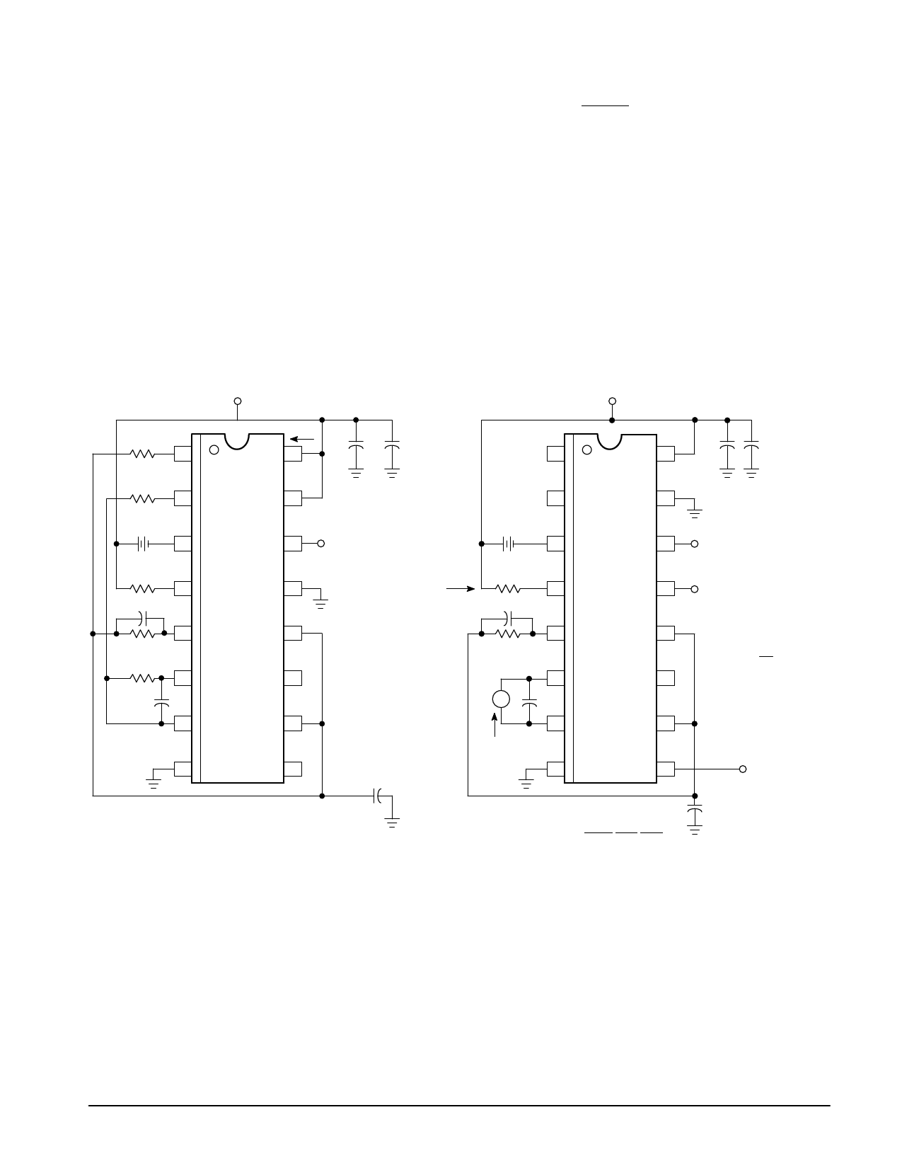
Figure 1. Power Supply Current
VCC
1.0 k
1
ICC 10 µF
0.1
16
1.0 k
2
60 mV
+– 3
15
14 Clock
5.0 k
4
0.1
5
10 k
10 k
6
0.05
7
13
CVSD
MC34115
12
11
10
8
9
0.1
Figure 2. IGCR – Gain Control Range and IInt –
Integrating Current
VCC
10 µF
0.1
1
16
2
VB
+–
3
IGC
Rx
4
0.1
5
10 k
6
A
0.05
IInt
7
8
15
14
13
CVSD
MC34115
12
11
10
9
Clock
(Note 2)
Digital Data
Input
+ IGC
VB
Rx
v Rx 5.0 k
Digital
Output
(Note 1)
0.1
NOTES: 1. Digital Output = Digital Data Input
2. For static testing, the clock is only necessary for
preconditioning to obtain proper state for a given input.
MOTOROLA ANALOG IC DEVICE DATA
5
Share Link: 