OM9369 查看數據表(PDF) - International Rectifier
零件编号
产品描述 (功能)
生产厂家
OM9369
International Rectifier

OM9369 Datasheet PDF : 14 Pages
| |||
OM9369
Modes of Operation
Figures 2 and 3, shown on the following pages,
provides schematic representations of typical voltage-
mode and current -mode applications for the OM9369
controller/driver.
Figure 2 represents the implemenation of a typical
voltage-mode controller for velocity control. A voltage or
speed command is applied to the noninverting input
of the error amplifier which is configured as voltage
follower. The ouput of the error amplifier is compared
to a pulse width modulated ramp, and since motor
speed is nearly proportional to the average phase
output voltage, the average speed is controlled via
duty cycle control. If a speed feedback loop is
required, the tachometer output can be connected to
the inverting input of the error amplifier via a loop
compensation network.
Figure 2 also shows the implementation of the
cycle-by-cycle current limit/overcurrent protection
feature of the OM9369. The load current is monitored
via the controller’s internal sense resistor. The
current sense signal is filtered and fed into the
current sense amplifier where the absolute value of
ISH-ISL is multiplied by two and biased up by 2.5V.
The output of the current sensor amplifier is
compared to a fixed reference, thus providing cycle-
by-cycle current limiting and/or overcurrent protection
as necessary. The typical peak current threshold
(ISL-ISH) is 0.2V; the typical over current threshold
(ISH-ISL) is 0.3V.
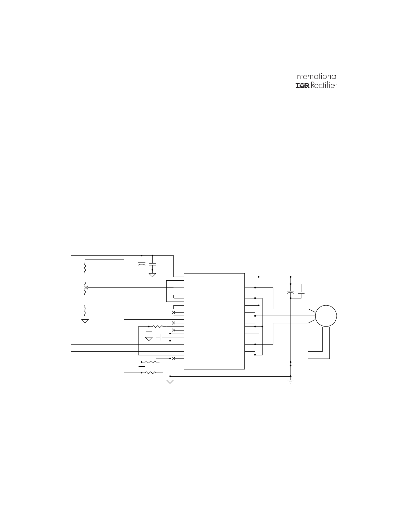
Fig 2: Implementation of a Voltage -Mode Controller
+15V
3.24k
COMMAND
1k
1.50k
FROM MOTOR HALL SENSORS
H3
H2
H1
10uF +
.1uF
.1uF
10k
.1uF
4700pF
232
232
1
2 Vcc
3 EA1-
4 EA2+
5 EA1+
6 VREF
7 EA2-
8 EA2_OUT
9 EA1_OUT
10 PWM_IN
11 OSCILLATOR
12 I_SENSE
13 ISH
14 ISL
15 QUAD_SEL
TACH_OUT
16
BRAKE
17
18 OV_COAST
19 SOFT_START
GROUND
20
H3_HALL_INPUT
21
22 H2_HALL_INPUT
23 H1_HALL_INPUT
SPEED_IN
24
25 DIRECTION
CSH
26
CSL
43
V_MOTOR
42
PHASE_A_OUT 41
PHASE_A_OUT
40
SOURCE_A 39
SOURCE_A
38
V_MOTOR
37
PHASE_B_OUT 36
PHASE_B_OUT
35
SOURCE_B 34
SOURCE_B
33
V_MOTOR
32
PHASE_C_OUT
31
PHASE_C_OUT
SOURCE_C 30
29
SOURCE_C
28
MOTOR_RETURN
27
MOTOR_RETURN
V_MOTOR
C_BUS
+
C_FILT
MOTOR
H1
H2
H3
HALL SENSORS
6
www.irf.com
Share Link: