P6KE10CA 查看數據表(PDF) - Daesan Electronics Corp.
零件编号
产品描述 (功能)
生产厂家
P6KE10CA Datasheet PDF : 5 Pages
| |||
P6KE6.8 THRU P6KE440CA
Features
· Plastic package has Underwriters Laboratory Flammability
Classification 94V-0
· Glass passivated junction
· 600W peak pulse power capability with a 10/100μS
waveform, reptition rate(duty cycle) : 0.01%
· Excellent clamping capability
· Low incremental surge resistance
· Fast response time : typically less than 1.0ps from 1 Volts to
V(BR) for uni-directional and 5.0ns for Bi-directional types
· Typical ID less than 1.0μA above 10V
· High temperature soldering guaranteed : 265℃/10seconds,
0.375"(9.5mm) lead length, 5lbs. (2.3kg) tension
Mechanical Data
· Case : DO-15 molded plastic body over passivated junction
· Terminals : Solder plated axial leads, solderable per
MIL-STD-750, method 2026
· Polarity : For uni-directional types the color band denotes
cathode end. which is positive with respect to the
anode under normal TVS operation
· Mounting Position : Any
· Weight : 0.014 ounce, 0.33 gram
POWER 600Watts
VOLTAGE 6.8 to 440 Volts
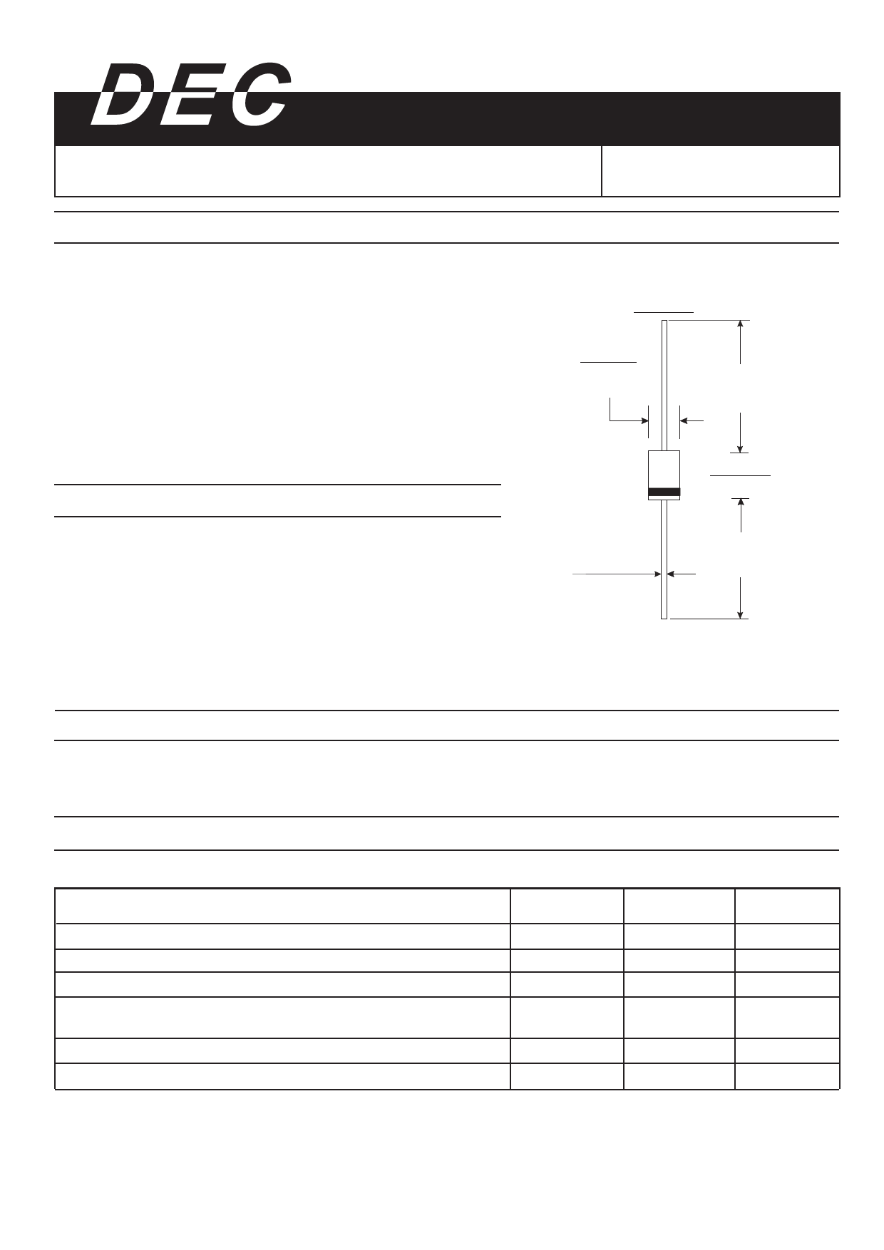
DO-15
0.140(3.6)
0.104(2.6)
DIA.
1.0(25.4)
MIN.
0.300(7.6)
0.230(5.8)
0.034(0.9)
0.028(0.7)
DIA.
1.0(25.4)
MIN.
Dimensions in inches and (millimeters)
Devices For Bidirectional Applications
· For bi-directional use C or CA suffix for types P6KE7.5 thru types P6KE440CA(e.g. P6KE10C, P6KE220CA),
electrical characteristics apply in both directions.
Maximum Ratings And Electrical Characteristics
(Ratings at 25℃ ambient temperature unless otherwise specified)
Peak power dissipation with a 10/1000μS waveform (Note 1. Fig. 3)
Peak pulse current with a 10/1000μS waveform (Note 1)
Steady state power dissipation at TL=75℃ lead length 0.375"(9.5mm) (Note2)
Peak forward surge current, 8.3mm single half sine-wave superimposed on
rated load(JEDEC method) undirectional (Note 3)
Maximum instantaneous forward voltage at 50A for unidirectional only(Note4)
Operating junction and storage temperature range
Symbols
PPPM
IPPM
PM(AV)
IFSM
VF
TJ,TSTG
Values
Min.600
See Table 1
5.0
100.0
3.5/50
-55 to +175
Notes:
(1) Non repetitive current pulse, per Fig.3 and derated above TA=25℃ per Fig.2
(2) Mounted on copper pads area of 1.6×1.6"(40×40mm) per Fig.5
(3) Measured on 8.3ms single half sine-wave or equivalent square wave, duty cycle=4 pulse per minute maximum
(4) VF=3.5 Volts max. for devices of V(BR)≤220V, and VF=5.0 Volts max. for devices of V(BR)>220V
Units
Watts
Amps
Watts
Amps
Volts
℃
Share Link: 