PI6C103 查看數據表(PDF) - Pericom Semiconductor
零件编号
产品描述 (功能)
生产厂家
PI6C103 Datasheet PDF : 12 Pages
| |||
PI6C103
111222333444555666777888999000111222333444555666777888999000111222333444555666777888999000111222111222333444555666777888999000111222333444555666777888999000111222333444555666777888999000111222111222333444555666777888999000111222333444555666777888P999000r111e222c333444is555666i777o888n999000111C222111l222o333c444555k666777S888999y000111n222t333h444555e666777s888i999z000e111r222333f444555o666r777888M999000111o222111b222i333l444e555666P777888C999000111s222
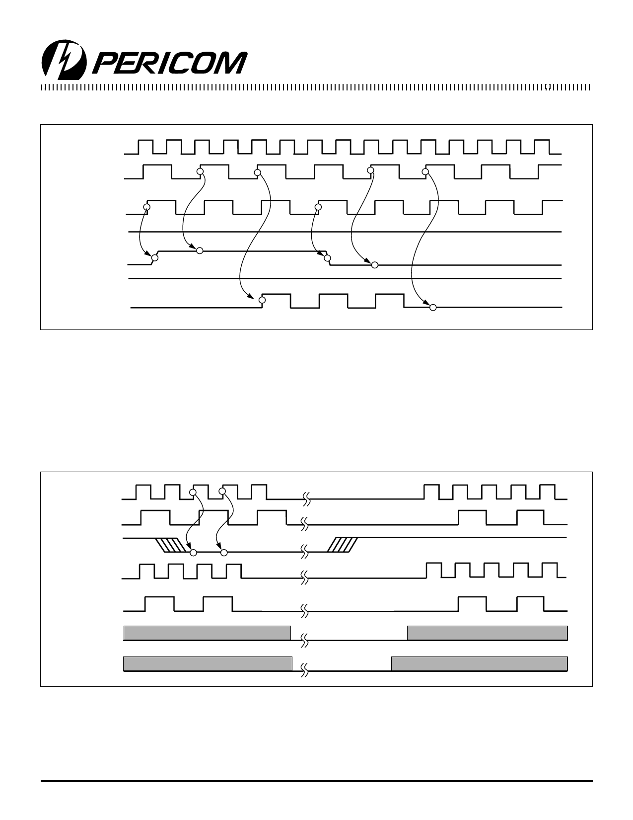
PCI_STOP# is an input signal used to turn off PCI clocks for low with a guaranteed full high pulse width. There is ONLY one rising
power operation. PCI clocks are stopped in the low state and started edge of external PCICLK after the clock control logic.
CPUCLK
(Internal)
PCICLK
(Internal)
PCICLK_F
(Free-running)
CPU_STOP#
PCI_STOP#
PWR_DWN#
PCICLK
(External)
Notes:
PCI_STOP# Timing Diagram
1. All timing is referenced to the CPUCLK.
2. PCI_STOP# signal is an input signal which must be made synchronous to PCI_F output.
3 Internal means inside the chip.
4. All other clocks continiue to run undisturbed.
5. PWR_DWN# CPU_STOP# are shown in a high state.
6. Diagrams shown with respect to 66 MHz. Similar operation as CPU = 100 MHz.
The PWR_DWN# is used to place the device in a very low power The power-on latency is less than 3ms. PCI_STOP# and
state. PWR_DWN# is an asynchronous active low input. Internal CPU_STOP# are dont cares during the power-down operations.
clocks are stopped after the device is put in power-down mode. The REF clock is stopped in the LOW state as soon as possible.
CPUCLK
(Internal)
PCICLK
(Internal)
PWR_DWN#
CPUCLK
(External)
PCICLK
(External)
VCO
Crystal
Notes:
PWR_DWN# Timing Diagram
1. All timing is referenced to the CPUCLK.
2. The Internal label means inside the chip and is a reference only.
3. PWR_DWN# is an asynchronous input and metastable conditions could exist. The signal is synchronized inside the part.
4. The Shaded sections on the VCO and the Crystal signals indicate an active clock.
5. Diagrams shown wth respect to 66 MHz. Similar operations as CPU = 100 MHz.
226
PS8315-2 04/08/99
Share Link: 