S5A 查看數據表(PDF) - TSC Corporation
零件编号
产品描述 (功能)
生产厂家
S5A Datasheet PDF : 2 Pages
| |||
CREAT BY ART
Pb
RoHS
COMPLIANCE
Features
For surface mounted application
Glass passivated junction chip.
Low forward voltage drop
High current capability
Easy pick and place
High surge current capability
Plastic material used carries Underwriters
Laboratory Classification 94V-0
High temperature soldering:
260℃/10 seconds at terminals
Green compound with suffix "G" on packing
code & prefix "G" on datecode.
Mechanical Data
Case: Molded plastic
Terminals: Pure tin plated, lead free.
Polarity: Indicated by cathode band
Packaging: 16mm tape per EIA STD RS-481
Weight: 0.21 grams
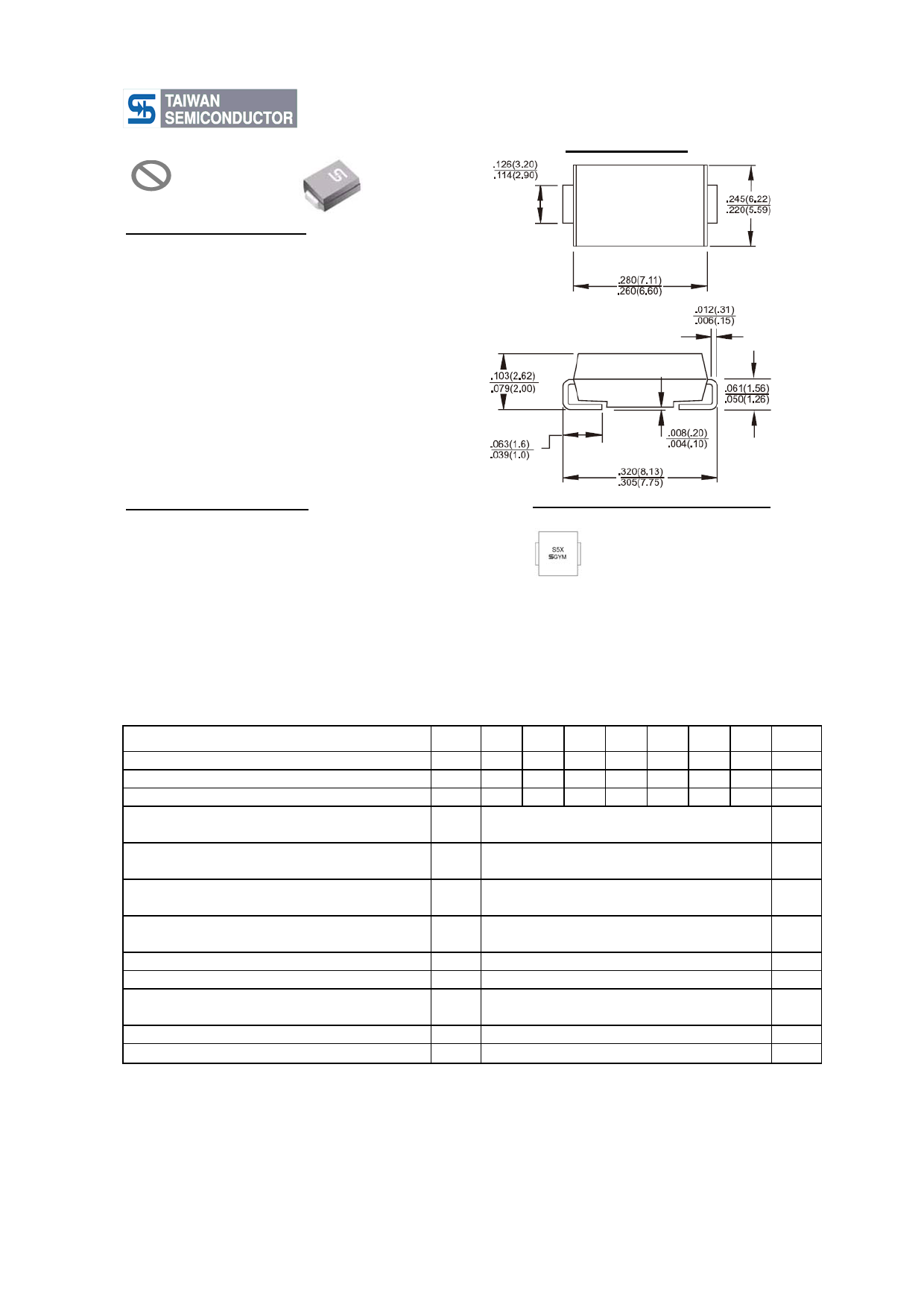
S5A - S5M
5.0 AMPS. Surface Mount Rectifiers
SMC/DO-214AB
Dimensions in inches and (millimeters)
Marking Diagram
S5X = Specific Device Code
G
= Green Compound
Y
= Year
M
= Work Month
Maximum Ratings and Electrical Characteristics
Rating at 25 ℃ ambient temperature unless otherwise specified.
Single phase, half wave, 60 Hz, resistive or inductive load.
For capacitive load, derate current by 20%
Type Number
Symbol S5A S5B S5D S5G S5J S5K S5M Units
Maximum Recurrent Peak Reverse Voltage
Maximum RMS Voltage
Maximum DC Blocking Voltage
VRRM 50 100 200 400 600 800 1000
V
VRMS
35
70 140 280 420 560 700
V
VDC
50 100 200 400 600 800 1000
V
Maximum Average Forward Rectified Current
IF(AV)
5
A
Peak Forward Surge Current, 8.3 ms Single Half Sine-
wave Superimposed on Rated Load (JEDEC method)
IFSM
Maximum Instantaneous Forward Voltage (Note 1)
@5A
VF
Maximum DC Reverse Current
at Rated DC Blocking Voltage
@ T A=25 ℃
@ T A=125 ℃
IR
Typical Reverse Recovery Time (Note 2)
Trr
Typical Junction Capacitance (Note 3)
Cj
Typical Thermal Resistance
RθJL
RθJA
Operating Temperature Range
Storage Temperature Range
TJ
TSTG
Notes: 1. Pulse Test with PW=300 usec, 1% Duty Cycle
2. Reverse Recovery Test Conditions: I F=0.5A, IR=1.0A, IRR=0.25A
3. Measured at 1 MHz and Applied V R=4.0 Volts
100
1.15
10
250
1.5
60
13
47
- 55 to + 150
- 55 to + 150
A
V
uA
uA
uS
pF
OC/W
OC
OC
Version:A12
Share Link: 