TEA1504 查看數據表(PDF) - Philips Electronics
零件编号
产品描述 (功能)
生产厂家
TEA1504 Datasheet PDF : 20 Pages
| |||
Philips Semiconductors
GreenChip™ SMPS control IC
Preliminary specification
TEA1504
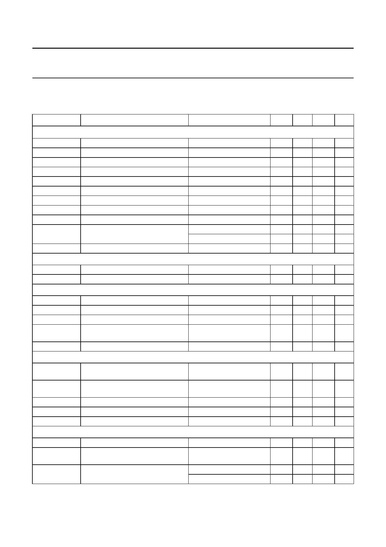
CHARACTERISTICS
Tj = −10 to +110 °C; VVi = 300 V; RREF = 24.9 kΩ (0.1%); VVaux = 8.6 to 13 V. Positive currents flow into the IC.
Negative currents flow out of the IC. All voltages are referenced to GND (pin 11).
SYMBOL
PARAMETER
CONDITIONS
MIN. TYP. MAX. UNIT
Start-up current source and Vaux management (pins 1 and 6)
Vstart(Vi)(min)
Vstart(Vaux)
VUVLO(Vaux)
Vhys(Vaux)
Ii(Vi)
Ioff(Vi)
Istart(Vaux)L
Istart(Vaux)H
lsup(Vaux)(oper)
Irestart(Vaux)
minimum start-up voltage on Vi
start-up voltage on Vaux
under-voltage lockout on Vaux
hysteresis voltage on Vaux
input current on Vi
off mode current on Vi
low start-up current on Vaux
high start-up current on Vaux
operating supply current on Vaux
restart current on Vaux
Vclamp(Vaux)
clamping voltage on Vaux
100 −
−
V
10.4 11 11.6 V
7.4 8.05 8.6 V
Vstart(Vaux) − VUVLO(Vaux)
normal operation
2.60 2.95 3.30 V
20
60 100 µA
VOOB < 1.95 V
150 350 550 µA
0 V < VVaux < 0.73 V
−270 −230 −190 µA
0.5 V < VVaux < Vstart(Vaux) −5.0 −3.0 −1.0 mA
no load on DRIVER (pin 4) 3.5 3.85 4.2 mA
in OCP mode
−600 −530 −460 µA
in burst standby mode
−2.5 −2.1 −1.7 mA
lVaux = 5 mA
15
−
18 V
Reference input (pin 8)
Vi(REF)
RREF(oper)
reference input voltage
operating reference resistor
2.37 2.47 2.57 V
16.9 24.9 33.2 kΩ
Oscillator
foscL
foscH
δmax
foscH/foscL
oscillator low frequency
low power operation mode 27.5 29 30.5 kHz
oscillator high frequency
normal mode
66 70 74 kHz
maximum duty cycle
ratio between oscillator high and low
frequencies
f = foscH
78 80 82 %
2.30 2.45 2.60
∆foscH
oscillator high frequency range
with changing RREF
50 70 100 kHz
Demagnetization management (pin 13)
Vth(DEM)
demagnetization comparator
threshold voltage on DEM
VDEM decreasing
50 65 80 mV
tP(DEM-BUF)
Ii(bias)(DEM)
Vclamp(DEM)(neg)
Vclamp(DEM)(pos)
propagation delay from DEM to output
buffer
input bias current on DEM
negative clamp voltage level on DEM
positive clamp voltage level on DEM
VDEM = 65 mV
IDEM = −500 µA
IDEM = 100 µA
300 500 700 ns
−0.5(1) −
−0.1(1) µA
−0.45 −0.35 0
V
2.3 2.6 2.9 V
Sample-and-hold (pin 13)
Ictrl(DEM)(oper)
Ith(sample)
tP(DEM-COMP)
operating control current on DEM
sample threshold current as % of
Ictrl(DEM)
propagation delay from DEM to
current comparator
lREF = 100 µA
90
100 110 µA
78 83 88 %
∆VDEM/∆t positive (500 V/µs) 170 450 730 ns
∆VDEM/∆t negative (10 V/µs) 20
90 160 ns
1999 Dec 07
11
Share Link: 